Fluid filter apparatus having filter media wound about a winding frame

a filter apparatus and fluid filter technology, applied in the field of fluid filter, can solve the problems of increasing the tendency of the first layer of fluid filter media to be pushed outward from the surface of the center board, affecting and difficult to create a secure, tight, seal between the first layer of fluid media and the center board, etc., to achieve the effect of improving the manufacturability and operational capability, and improving the environmental friendliness of the filter elemen

Active Publication Date: 2008-06-12
BALDWIN FILTERS
View PDF43 Cites 33 Cited by
  • Summary
  • Abstract
  • Description
  • Claims
  • Application Information

AI Technical Summary

Benefits of technology

[0013]The present invention provides an improved filter apparatus and method, through utilization of a filter element having a winding frame and a length of fluted filter media wound about the frame with the flutes of the media oriented substantially longitudinally, to thereby provide for filtration of a flow of fluid passing axially through the filter element. In some forms of the invention, the winding frame is a substantially open, truss-like structure. Use of a winding frame, rather than the center boards or other types of cores used in prior filter elements, provides a number of advantages, including, but not limited to improvements in manufacturability and operational capability and improved environmental friendliness of the filter element.

Problems solved by technology

For cores in race track shaped elements, however, such as the center board used in the Gieseke patent, the inherent tendency of the filter media to bow outward may make it difficult to create a secure, tight, seal between the first layer of the media and the center board.
In practice, however, the corrugated section of the center board of Gieseke may, in fact, make it more difficult to achieve the desired fit between the first layer of fluid media and the outer surface of a non-cylindrical core, by interfering with the ability of the media to move freely while being pulled by a winding tensioning force across the surface of the core during the winding operation.
In addition, fluted filter media, of the type typically used in such filter elements, is fabricated from layers of paper-like material by processes which are not amenable to accurate control of dimensional tolerances, with the result being that, in actual practice, the fluted media may not fit well into the corrugations of the center board, thereby causing an additional tendency of the first layer of media to be pushed outward away from the surface of the center board.
As a further difficulty, the corrugations of Gieseke must be closely matched to a given flute profile, thereby making it difficult to utilize different flute spacing and shapes with a given center board, which in turn can drive up inventory and manufacturing costs.
Because filter elements of this type are often disposable, so that they may be readily replaced at appropriate intervals, additional manufacturing complexity and cost, resulting in increase replacement cost of the element, is highly undesirable and can be a significant detriment to successful competition in the marketplace.
The center board of the Gieseke patent does not meet these requirements.
The configuration of the cutout of Gieseke is an inefficient drive mechanism, in that the winding torque from the spindle is apparently applied only to the sidewalls of the cutout, which are located closely adjacent to the winding axis and essentially formed by the thickness of the center board.
Such an inefficient drive mechanism may make it difficult to apply sufficient winding torque, without damaging the center board, to maintain a winding tension in the filter media which is high enough to pull the media into intimate contact with the outer surface of the center board or previously wound layers of media.
The core construction of Krisko also appears to include a substantial volume of excess material, making such a core construction undesirably expensive to produce and heavier than necessary.
The core construction of Krisko also results in a significant amount of extra material which must be disposed of or incinerated when the filter element is replaced.

Method used


Image

  • Fluid filter apparatus having filter media wound about a winding frame
  • Fluid filter apparatus having filter media wound about a winding frame
  • Fluid filter apparatus having filter media wound about a winding frame

Examples


Embodiment Construction

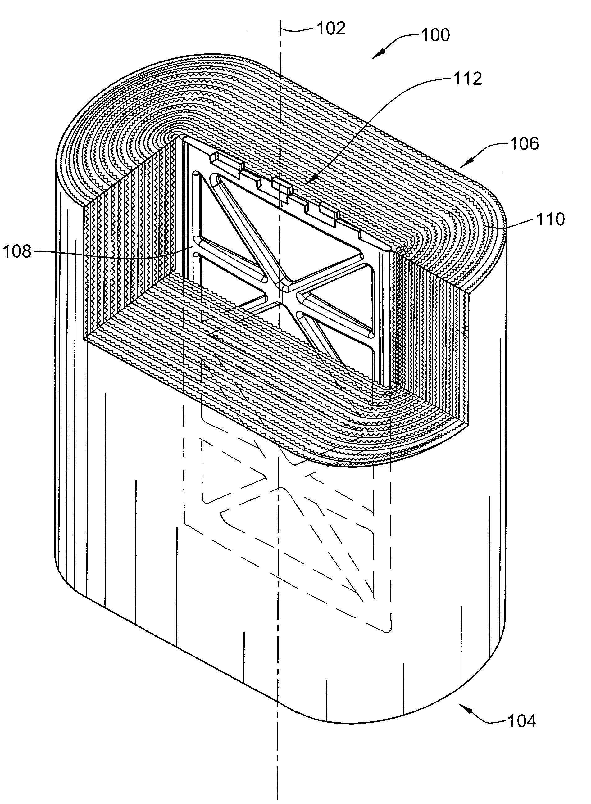
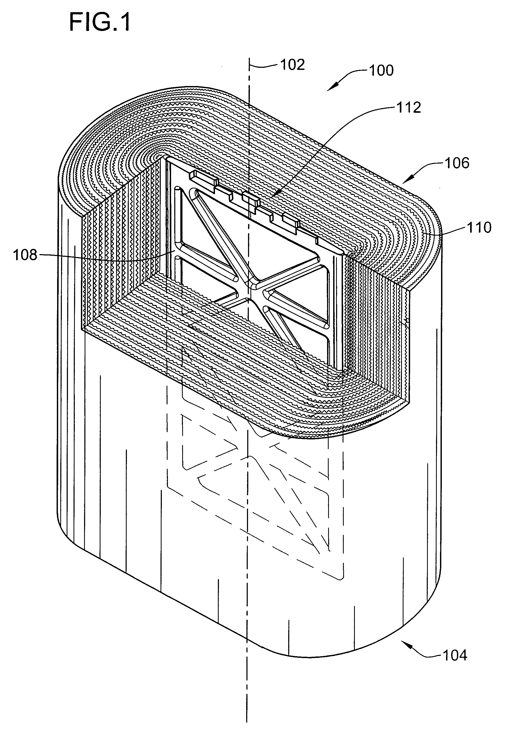
[0038]FIG. 1 shows a first exemplary embodiment of the invention in the form of a filter element 100 defining a longitudinal axis 102 and first and second axial ends 104, 106 of the filter element 100. The exemplary embodiment of the filter element 100 includes a winding frame 108, and a length of fluted filter media 110 wound about the frame 108, with the flutes of the fluted filter media being oriented substantially longitudinally to the longitudinal axis of the filter element 100, to thereby provide for filtration of a flow of fluid passing axially through the filter element 100.

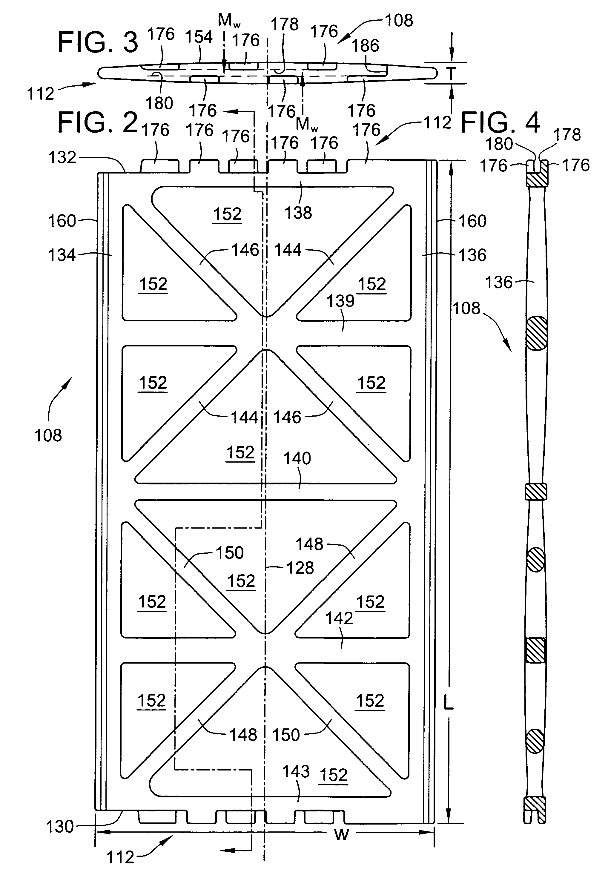
[0039]As shown in FIGS. 1-7, and described in more detail below, the winding frame 108 of the exemplary embodiment 100 of the filter element is a substantially open, truss-like structure, having a smooth advantageously shaped outer periphery, allowing the media 110 to be effectively pulled into intimate contact with the outer periphery of the winding frame 100 by a winding tension force applied to the med...


PUM

PropertyMeasurementUnit
lengthaaaaaaaaaa
widthaaaaaaaaaa
thicknessaaaaaaaaaa

Abstract

A filter apparatus and method utilize a filter element having a central winding frame and a length of fluted filter material wound about the frame with the flutes of the media oriented substantially longitudinally, to thereby provide for filtration of a flow of fluid passing axially through the filter element. The winding frame is a substantially open, truss-like structure, having a smooth outer periphery and an axially extending winding feature to facilitate pulling the media into intimate contact with the smooth outer periphery during fabrication of the filter element. A leading edge of the filter media is anchored to a leading edge of the frame by a length of tape.

Description

FIELD OF THE INVENTION[0001]This invention relates to fluid filters for removing particulate matter from a flow of fluid in liquid or gaseous form, including filters of the type used for filtering inlet air supplied to machinery such as engines and compressors.BACKGROUND OF THE INVENTION[0002]In one commonly utilized form of a filter element, the filter element defines a longitudinal axis and first and second axial ends of the filter element, with the filter element including a central core, and a length of fluted filter media wound about the central core, with the flutes of the media oriented substantially longitudinal, to thereby provide for filtration of a flow of fluid passing axially through the filter element. Such filter elements are typically installed within a housing, or duct, in such a manner that the filter element can periodically be removed for cleaning or replacement with a fresh filter element. A seal between the filter element and the housing is typically provided, ...

Claims


Application Information

Patent Timeline
Patent Type & Authority Applications(United States)
IPC IPC(8): B01D29/07
CPCB01D25/001B01D46/0001B01D46/527B01D25/24
Inventor MERRITT, STEVEN J.SWANSON, KYLE
Owner BALDWIN FILTERS
Why Eureka
Try Eureka