Pneumatic Spring Comprising a Ball Joint

a technology of pneumatic springs and ball joints, applied in the field of pneumatic springs, can solve the problems of increased internal friction, noise generation, leakage,

Inactive Publication Date: 2008-06-12
ZF FRIEDRICHSHAFEN AG
View PDF9 Cites 17 Cited by
  • Summary
  • Abstract
  • Description
  • Claims
  • Application Information

AI Technical Summary

Benefits of technology

[0006]The bearing play between the bearing shell and the spherical bearing element can be adjusted precisely to the desired value, so that the friction problem is solved.
[0007]In a concrete embodiment of the invention, the bearing shell has a conical gripping surface on the outside, against which the clamping element acts. The clamping element exerts an axial tensioning movement which reduces the diameter of the bearing shell.
[0011]The bearing shell is elastic, so that the adjusting forces which must be exerted on the tension ring remain with limits. If, for example, the friction increases because of the heating of the ball joint, the tension ring can be loosened slightly. The bearing shell, because of its intrinsic elasticity, will assume an appropriately modified contour.
[0014]In another advantageous embodiment, a seal separates the spring space from the bearing shell. The pretension of the bearing shell is therefore independent of the pretension of the seal, so that there can be no conflict between the goal of obtaining the desired bearing play and the goal of sealing the pneumatic spring effectively.
[0021]If it is necessary to remove the ball joint to allow repairs, one end of the protective bellows, which is attached to the tension ring, can be removed very easily to provide free access to the ball joint. A simple spring clamp holds the end of the protective bellows firmly in place on the tension ring.

Problems solved by technology

In this ball joint, dimensional deviations lead to increased internal friction or, in the other extreme case, in which the seal is not adequately pretensioned between the bearing shells, to the generation of noise and to leakage.

Method used


Image

  • Pneumatic Spring Comprising a Ball Joint
  • Pneumatic Spring Comprising a Ball Joint
  • Pneumatic Spring Comprising a Ball Joint

Examples


Embodiment Construction

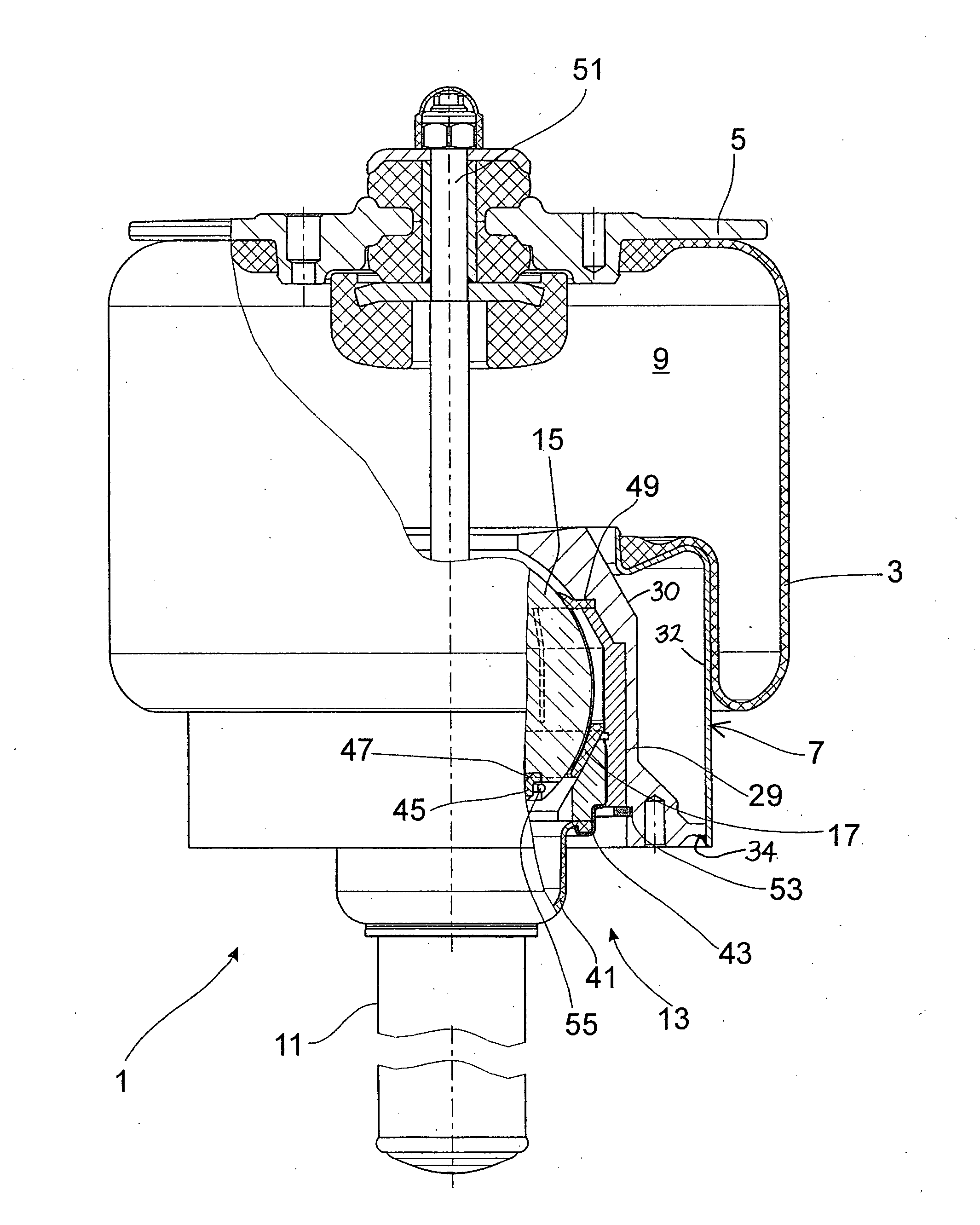
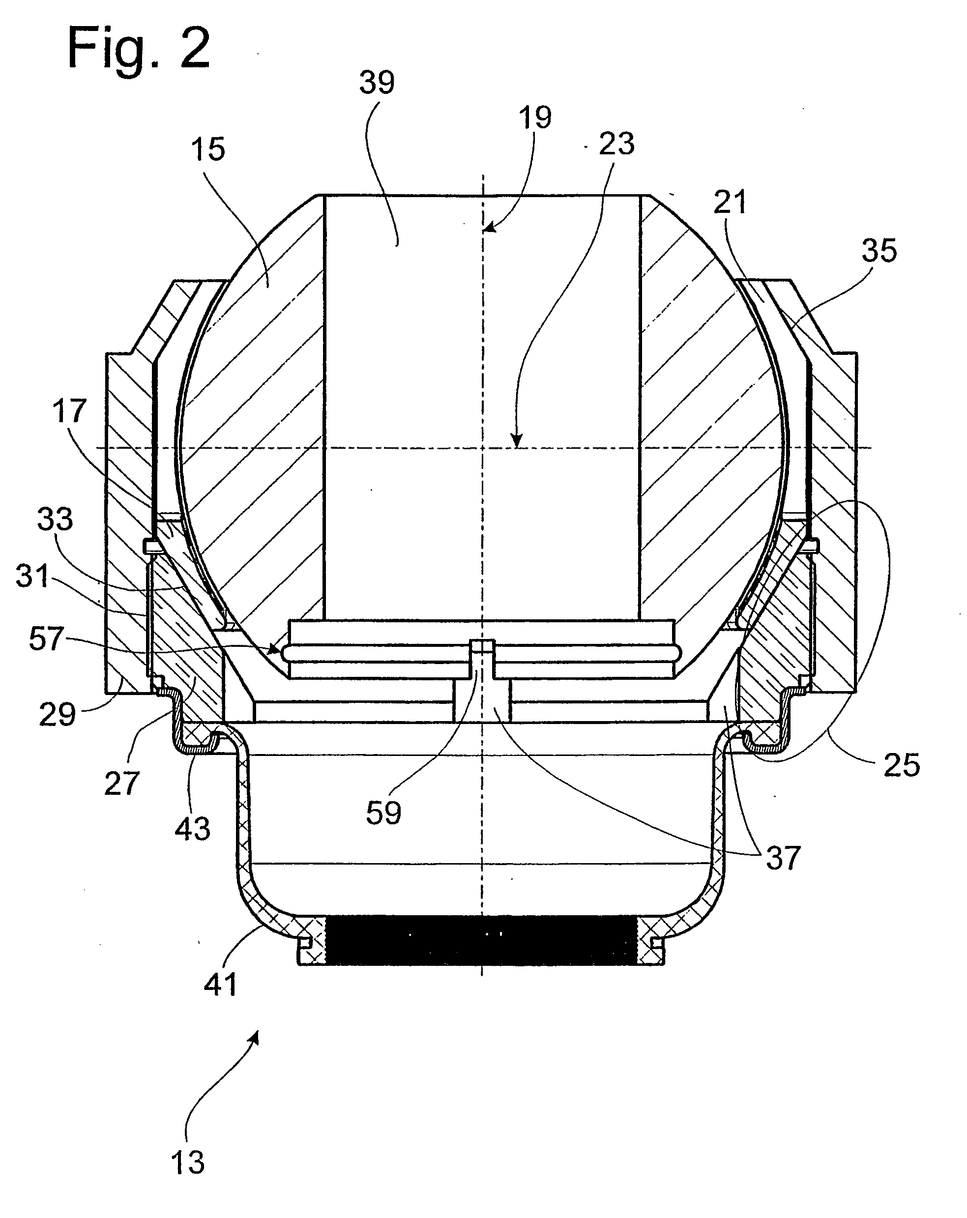
[0005]According to the invention, the task is accomplished in that the bearing shell can be tightened onto the spherical bearing element by means of a clamping element.

[0006]The bearing play between the bearing shell and the spherical bearing element can be adjusted precisely to the desired value, so that the friction problem is solved.

[0007]In a concrete embodiment of the invention, the bearing shell has a conical gripping surface on the outside, against which the clamping element acts. The clamping element exerts an axial tensioning movement which reduces the diameter of the bearing shell.

[0008]So that the bearing shell will be radially pretensioned in a uniform manner, the clamping element is formed by a tension ring. The clamping element is braced against a support sleeve and is itself therefore well centered.

[0009]The spherical bearing element, the bearing shell, the tension ring, and the support sleeve form a closed structural unit, because the support sleeve cooperates with a...


PUM


Abstract

The invention relates to a pneumatic spring (1) comprising a roll bellow (3) which is secured to an unrolling tube (7) and which forms a spring space therewith (9). The unrolling tube (7) is connected to a base part (11) by means of a ball joint (13) which comprises a spherical bearing element (15) contained in the bearing shell. The bearing shell (17) can be adjusted in relation to the spherical bearing element (15) by means of a clamping element (25).

Description

TECHNICAL AREA[0001]The invention pertains to a pneumatic spring according to the introductory clause of claim 1.PRIOR ART[0002]FIG. 6 of DE 199 59 839 A1 shows a pneumatic spring with a rolling bellows attached to a roll-down tube. A ball joint is installed between a base part—in this case, a vibration damper—and the roll-down tube. The ball joint consists of a spherical bearing element, which is located in a two-part bearing shell. A seal, which seals off the spring space of the pneumatic spring, is present between the two halves of the bearing shell.[0003]In this ball joint, dimensional deviations lead to increased internal friction or, in the other extreme case, in which the seal is not adequately pretensioned between the bearing shells, to the generation of noise and to leakage.[0004]The task of the present invention is to improve the ball joint especially intended for pneumatic springs in such a way that the problems familiar from the prior art with respect to friction and lea...

Claims


Application Information

Patent Timeline
Patent Type & Authority Applications(United States)
IPC IPC(8): F16F9/05B60G11/28
CPCB60G11/28B60G15/14B60G2202/314F16F2230/14B60G2204/416F16F9/0454B60G2204/1262
Inventor KOLB, WOLFGANGGEYER, ULRICHLOESCHE, CHRISTIANRICHTER, REINHARDBRUNNEKE, HANS-GERD
Owner ZF FRIEDRICHSHAFEN AG
Why Eureka
Try Eureka