
Mobile Terminal and Method of Charging Battery Mounted in Mobile Terminal

Inactive Publication Date: 2008-06-12
LENOVO INNOVATIONS LTD HONG KONG
View PDF2 Cites 10 Cited by
  • Summary
  • Abstract
  • Description
  • Claims
  • Application Information

AI Technical Summary

Benefits of technology

[0012]In view of the above-mentioned problems which occur when a conventional mobile terminal is charged, it is an object of the present invention to provide a mobile terminal, a method of charging a battery mounted in a mobile terminal, and a program for executing the method, all of which are capable of shortening a period of time necessary for charging a battery, and preventing a temperature of a mobile terminal from rising.
[0014]In the mobile terminal in accordance with the present invention, since a temperature in the case is detected by the temperature sensor, it is possible to detect a temperature of an entirety of a mobile terminal taking into consideration calorific power produced by electronic parts other than the charging circuit. Furthermore, since the charge controller controls a current to be supplied to the battery, in accordance with a temperature in the case, a current to be supplied to the battery is controlled within a range of a temperature allowable for a mobile terminal. Thus, when electronic parts produce calorific power in a relatively great amount, it would be possible to reduce a current to be supplied to the battery to thereby prevent a temperature of an entirety of a mobile terminal from rising. When electronic parts produce calorific power in a relatively small amount, it would be possible to increase a current to be supplied to the battery to thereby shorten a period of time necessary for charging the battery.
[0016]When a temperature in the case detected by the temperature sensor is higher than a predetermined switch-temperature, it means that electronic parts arranged in the case produce calorific power in a great amount. Hence, the charge controller selects a first current which is relatively small, as a current to be supplied to a battery, to thereby reduce calorific power produced by a battery, and accordingly, prevent a temperature of an entirety of a mobile terminal from rising. In contrast, when a temperature in the case detected by the temperature sensor is lower than the predetermined switch-temperature, it means that electronic parts arranged in the case produce calorific power in a small amount. Hence, the charge controller selects a second current which is relatively great, as a current to be supplied to a battery, to thereby rapidly charge a battery for shortening a period of time necessary for charging a battery.
[0018]The first current and the second current may be fixed, or may be variable. By setting the first and second currents to be variable, it would be possible to vary a weight in preventing a temperature of an entirety of a mobile terminal from rising, and shortening a period of time necessary for charging a battery, in accordance with a condition in which a mobile terminal is used and / or an environment in which a mobile terminal is used.
[0022]A stop-temperature is determined lower than the above-mentioned switch-temperature, for instance. When a temperature in the case detected by the temperature sensor is higher than a predetermined stop-temperature, it means that electronic parts arranged in the case produce calorific power in a great amount. Hence, the charge controller stops charging the battery to thereby prevent the battery from producing calorific power, and accordingly, prevent a temperature of an entirety of a mobile terminal from rising. In contrast, when a temperature in the case detected by the temperature sensor is lower than the predetermined stop-temperature, it means that electronic parts arranged in the case produce calorific power in a small amount. Accordingly, the charge controller carries out charging the battery.
[0024]This arrangement makes it possible to accurately detect a temperature in the case.

Problems solved by technology

Hence, if electronic parts other than a charging circuit, and a battery simultaneously produce calorific power, a temperature of a mobile terminal excessively rises, resulting in that a surface temperature of a case also rises, and a user of a mobile terminal feels ill when he / she makes direct touch with a surface of a case.
In order to solve this problem, if a target voltage of a battery and a target temperature of a battery are set low, a current for charging a battery is reduced even when electronic parts other than a charging circuit do not produce calorific power, resulting in another problem that it takes too much time to charge a battery.

Method used


Image

  • Mobile Terminal and Method of Charging Battery Mounted in Mobile Terminal
  • Mobile Terminal and Method of Charging Battery Mounted in Mobile Terminal
  • Mobile Terminal and Method of Charging Battery Mounted in Mobile Terminal

Examples


Embodiment Construction

[0045]Preferred exemplary embodiments in accordance with the present invention will be explained hereinbelow with reference to drawings.

[0046]The mobile terminal in accordance with the present invention is applied to a mobile phone in exemplary embodiments explained hereinbelow. In explanation made with reference to drawings, the same parts have been provided with the same reference numerals, and will not be explained in duplicate.

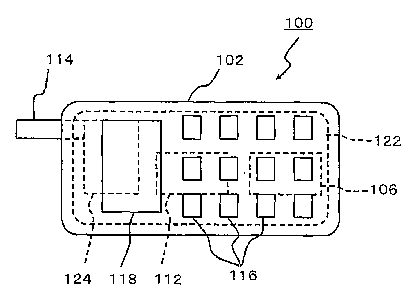
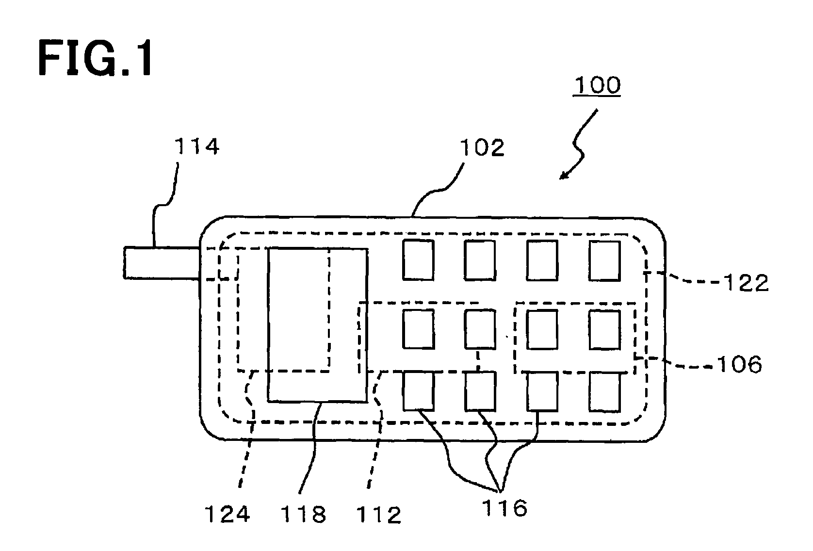
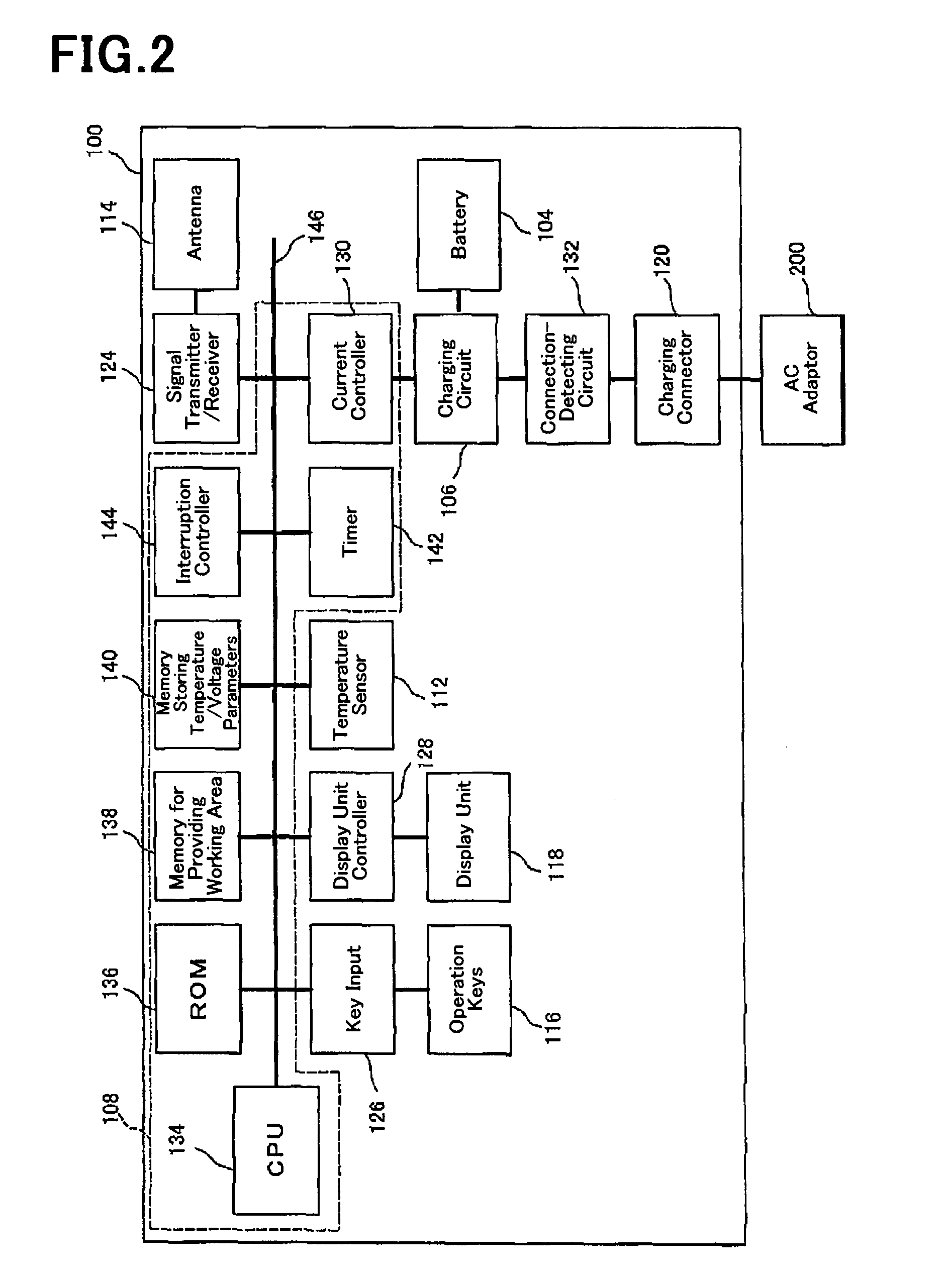
[0047]FIG. 1 is a plan view of a mobile phone 100 as a mobile terminal in accordance with the first exemplary embodiment of the present invention, and FIG. 2 is a block diagram of the mobile phone 100.

[0048]As illustrated in FIGS. 1 and 2, the mobile phone 100 is comprised of a case 102 in which electronic parts defining the mobile phone 100 are arranged, a battery 104 mounted in the case 102, a charging circuit 106 supplying a current derived from electric power supplied from an AC adaptor 200 electrically connected to a later mentioned charging connector...


PUM


Abstract

In order to shorten a period of time necessary for charging a battery, and further, to prevent a temperature of a mobile terminal from raising, the mobile terminal 100 is comprised of a case 102 in which electronic parts are arranged, a battery 104 mounted in the case 102, a battery-charging circuit 106 supplying a current to the battery 104, a charge controller 108 allowing the battery-charging circuit 106 to charge the battery 104 or stopping the battery-charging circuit 106 from charging the battery 104, and a temperature sensor 112 detecting a temperature in the case 102, wherein the charge controller 108 controls the current to be supplied to the battery 104, in accordance with a temperature detected by the temperature sensor 112.

Description

BACKGROUND OF THE INVENTION[0001]1. Field of the Invention[0002]The invention relates to a mobile terminal, and more particularly to a method of charging a battery mounted in a mobile terminal[0003]2. Description of the Related Art[0004]A mobile terminal such as a mobile phone, PHS (Personal Handy-phone System), PDA (Personal Data Assistance or Personal Digital Assistant) and a note-type personal computer has been designed to include a battery in a case thereof for supplying electric power to electronic parts constituting a mobile terminal. A battery is designed to be able to be electrically connected to an external AC power source, and to be charged when electrically connected to the AC power source.[0005]A system for charging a battery is suggested, for instance, in Japanese Patent Application Publications Nos. 2002-58174 and 2001-136675 (patent references 1 and 2).[0006]In the system suggested in patent reference 1, a temperature around a capacitor is detected, and a voltage of a...

Claims


Application Information

Patent Timeline
IPC IPC(8): H02J7/00H01M10/44
CPCH01M10/443H02J7/047H01M10/486H01M10/46H02J7/007194Y02E60/10H02J7/04H02J7/007192
Inventor ETO, YASUTAKA
Owner LENOVO INNOVATIONS LTD HONG KONG
Learn More