Network for automated meter reading

a technology of automated metering and network, applied in the integration of power network operation system, sustainable buildings, instruments, etc., can solve the problems of customer complaints, difficult to cost effectively measure commodity usage for each user, and difficult for the service person to access the meter for reading

Inactive Publication Date: 2008-06-12
ITRON NETWORKED SOLUTIONS INC
View PDF11 Cites 39 Cited by
  • Summary
  • Abstract
  • Description
  • Claims
  • Application Information

AI Technical Summary

Benefits of technology

[0012]In another embodiment, the meter is also able to communicate directly with the utility through the variety of commercially available communication network interface modules that plug into the meter's backplane or bus system. For example, these modules might include a narrowband personal communication services (PCS) module or a power line carrier (PLC) module. For these modules, a gateway node is not necessary to complete the communication link between the meter and the utility. One class of PLC modu

Problems solved by technology

Sometimes it may be difficult for the service person to access the meter for reading, inspection and maintenance.
These estimated billings often lead to customer complaints.
This makes it difficult to cost effectively measure commodity usage for each user to promote fair billing and encourage conservation.
Manual reading of meters is highly labor intensive, inefficient and expensive.
However, most of these prior art systems have achieved little success.
The use of existing telephone lines and power lines to communicate commodity usage data to a utility have encountered significant technical difficulties.
In a telephone line system, the meter data may interfere with the subscriber's normal phone line operation, and requires cooperation between the telephone company and the utility company for shared use of the telephone lines.
A telephone line communication link also requires a hard wire connection between the meter and the main telephone line, incr

Method used


Image

  • Network for automated meter reading
  • Network for automated meter reading
  • Network for automated meter reading

Examples


Embodiment Construction

[0029]To facilitate an understanding of the concepts that constitute the invention disclosed herein, implementations of the invention are described in the context of measuring usage and other characteristics of electricity delivered to a premises. It will be appreciated that the described implementations are exemplary, and that the invention is applicable to the measurement and monitoring of other commodities provided by utilities, such as natural gas, water, etc.

Electronic Electric Meter

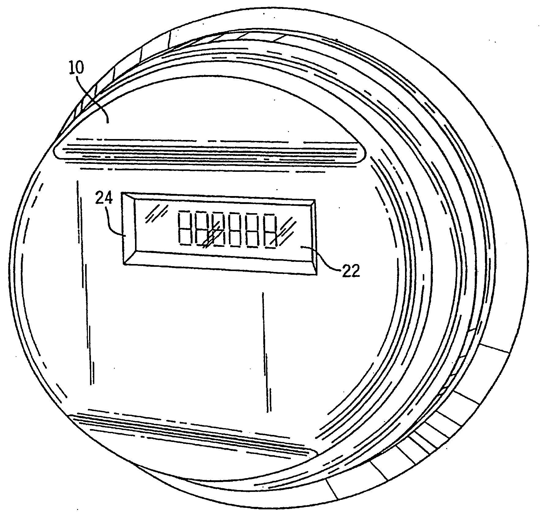
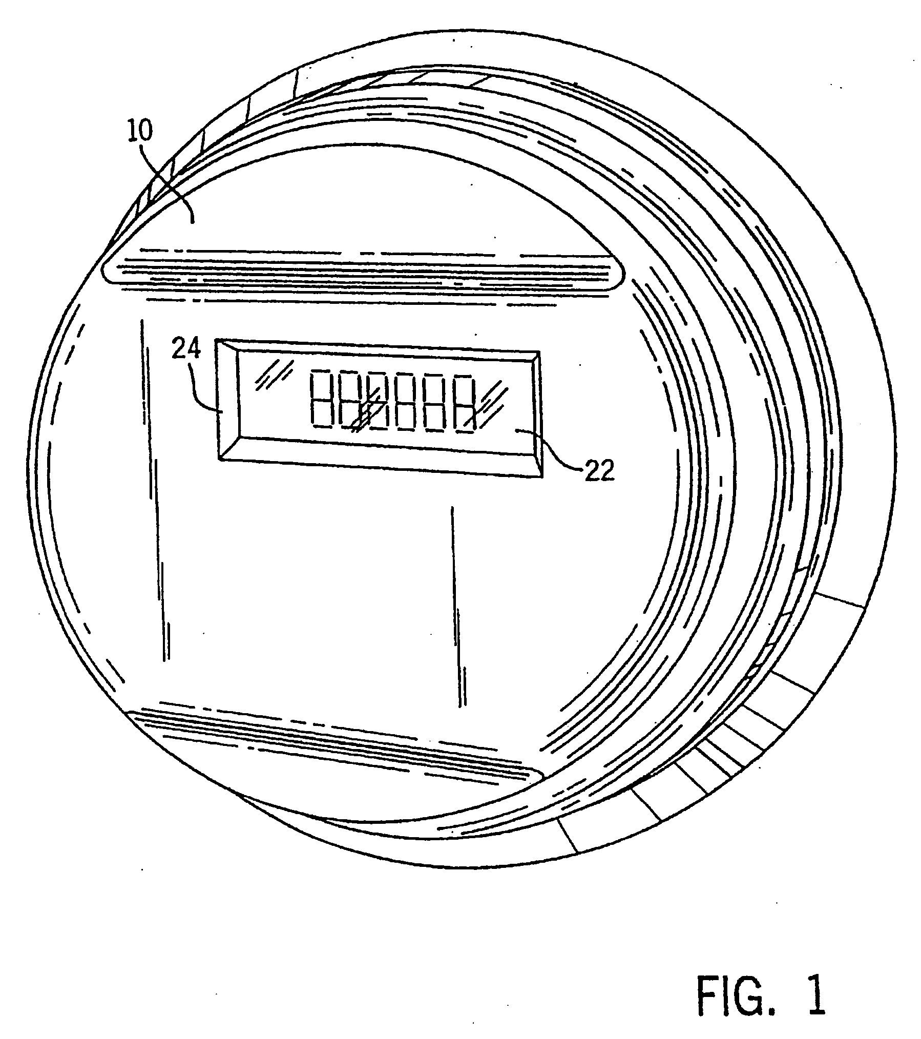
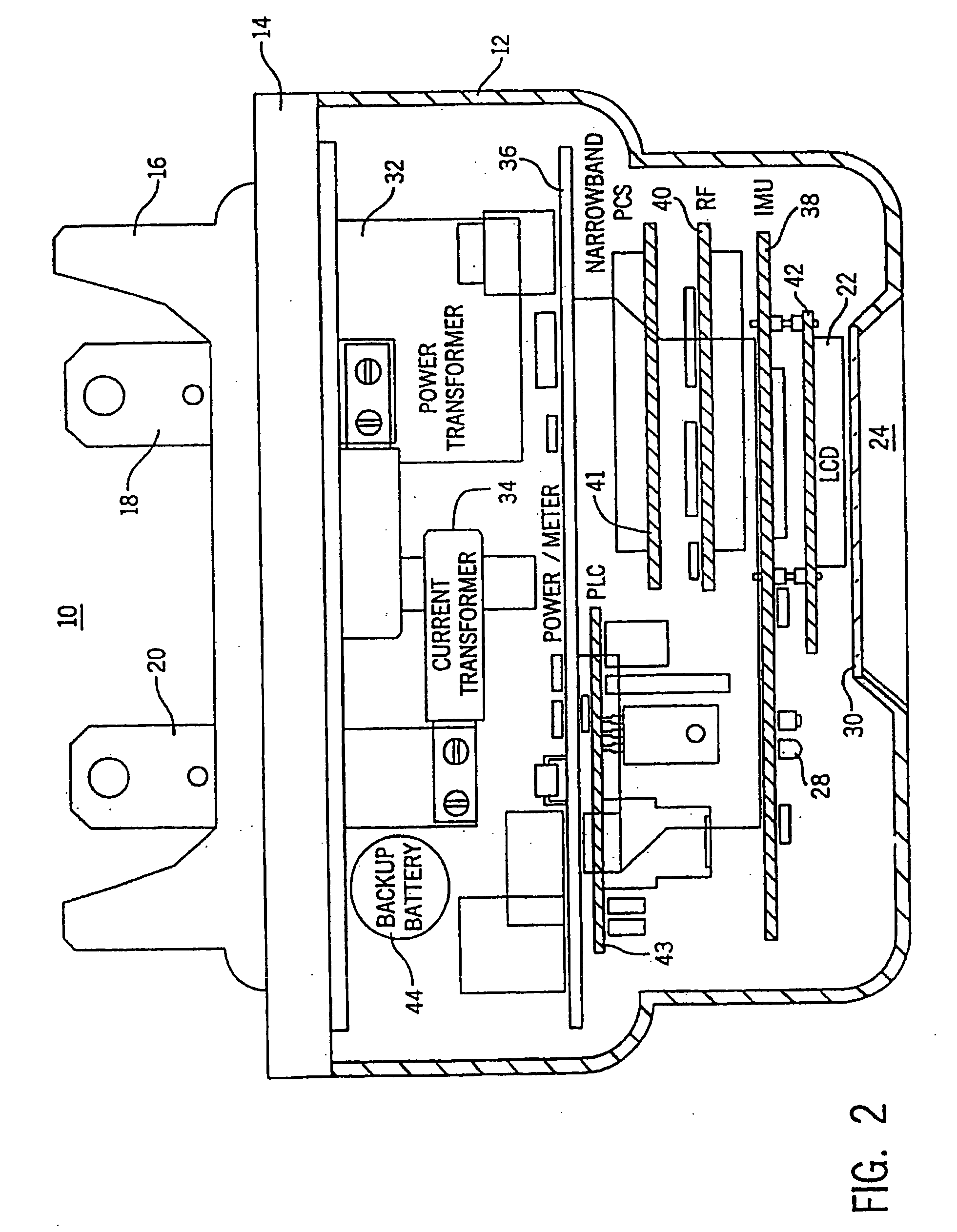
[0030]FIGS. 1 and 2 show a fully integrated, self-contained electronic electric meter 10 for measuring electricity usage and monitoring power quality. The meter 10 is operable for both single phase and three phase electric power installations. The meter 10 includes a top cover 12 attached to a meter base 14. Extending outwardly from the meter base 14 is a mounting frame 16 and a pair of terminals 18, 20. The meter 10 easily retrofits into existing meter sockets by insertion of terminals 18, 20 into ...


PUM


Abstract

A networked automatic meter reading system includes a plurality of meters that measure commodity usage and monitor quality parameters for transmission to a utility over a two-way local area network (LAN) to a remotely located gateway node. The gateway node transmits this data to the utility over a commercially available fixed wide area network (WAN). The meter can also provide direct communication to the utility over a commercially available network interface that plugs into the meter, bypassing the local area network communication link and gateway node. The meter also provides an interface to an in-premises network that communicates with consumer devices in a household or other facility. The gateway performs routing analysis of packets to determine preferred routing paths, and disseminates this information to the meters.

Description

CROSS-REFERENCE TO RELATED APPLICATIONS[0001]This document is a continuation-in-part of U.S. application Ser. No. 11 / 894,333, filed Aug. 21, 2007, which is a divisional of U.S. application Ser. No. 10 / 672,781, filed Sep. 26, 2003, now U.S. Pat. No. 7,277,027, which is a continuation of U.S. application Ser. No. 10 / 319,856, filed Dec. 13, 2002, now abandoned, which is a continuation of U.S. application Ser. No. 09 / 242,792, filed Feb. 23, 1999, now U.S. Pat. No. 6,538,577, the entire contents of each of which are hereby incorporated by reference.BACKGROUND OF THE INVENTION[0002]The present invention relates to a system for the automated measurement and management of usage of a commodity. More particularly, the invention relates to an electronic meter for measuring consumption of a commodity such as electricity, and a network for communicating that usage data and other related information to a utility over a two-way wireless local area network (LAN) to a remotely located gateway node t...

Claims


Application Information

Patent Timeline
IPC IPC(8): G08B23/00
CPCG01D4/004Y02B90/242Y04S20/322Y02B70/3266Y04S20/42Y02B90/246Y04S20/242Y04S20/40Y02B90/245Y02B70/30Y02B90/20Y04S20/30
Inventor VASWANI, RAJFLAMMER, GEORGEDRESSELHUYS, DONN R.
Owner ITRON NETWORKED SOLUTIONS INC
Why Eureka
Try Eureka