
Apparatus of driving plasma display panel

a technology of plasma display panel and apparatus, which is applied in the direction of static indicating device, casing/cabinet/drawer details, instruments, etc., can solve the problems of generating strong discharge entailing an undesired shape of brightness point, erroneous brightness point fire, etc., and achieve accurate temperature detection and stab driving

Inactive Publication Date: 2008-06-12
LG ELECTRONICS INC
View PDF13 Cites 6 Cited by
  • Summary
  • Abstract
  • Description
  • Claims
  • Application Information

AI Technical Summary

Benefits of technology

[0024]Accordingly, it is an object of the present invention to provide an apparatus of driving a plasma display panel capable of accurately detecting a temperature of the plasma display panel for a stably driving of the plasma display panel.
[0028]In the apparatus, the molding product uniformly keeps a gap between the heat-proof plate and the substrate.

Problems solved by technology

Recently, various flat panel devices have been developed that reduce weight and bulk, which are drawbacks of the cathode ray tube (CRT).
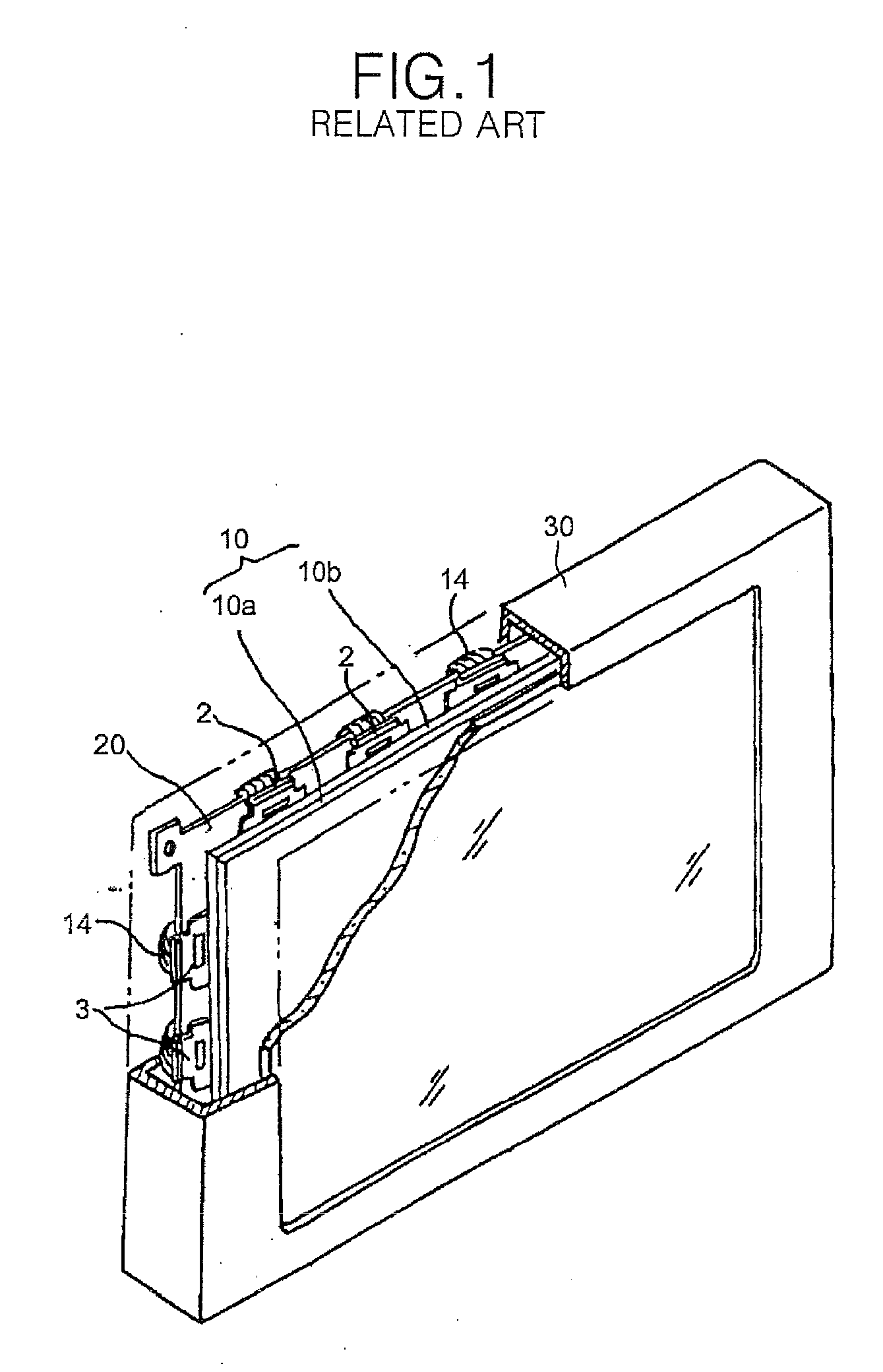
However, if the related art PDP is operated at a low temperature, then a brightness point erroneous fire occurs.
It has been supposed that such a brightness point erroneous fire occurs because a motion of particles becomes dull at the low temperature.
In other words, a strong discharge entailing an undesired shape of brightness point is generated in the sustain period due to the wall charges formed excessively in the discharge cells.
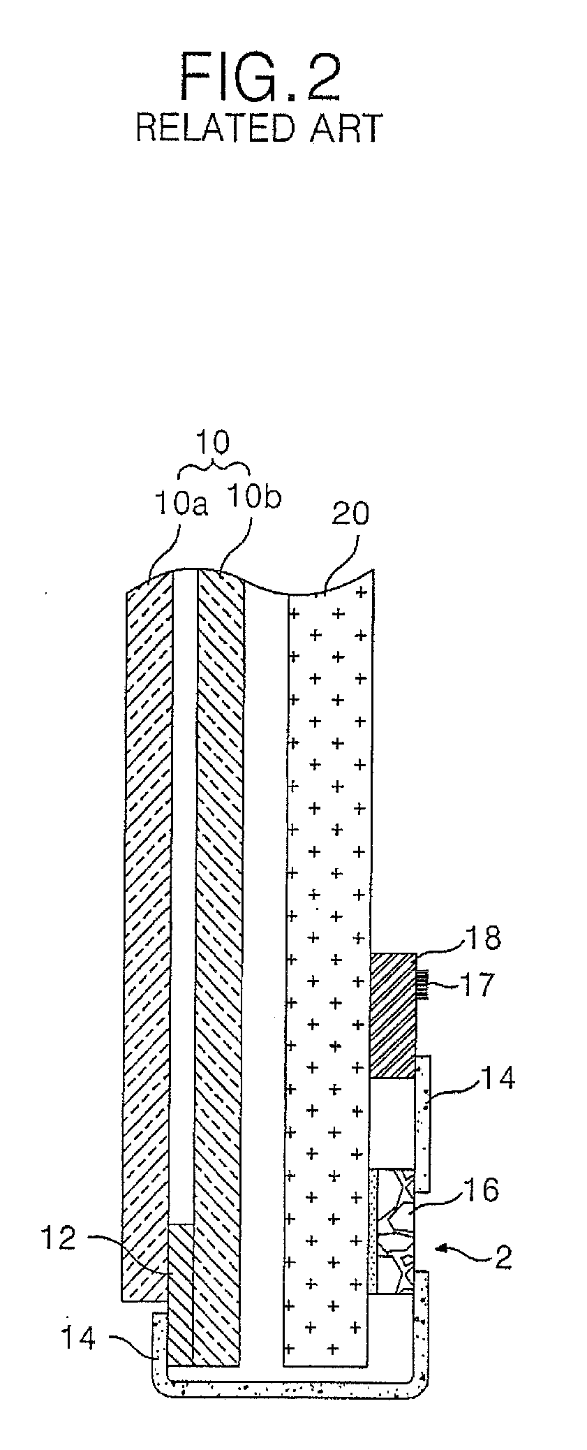
That is, since the temperature sensor 17 is built in the PCB 18 and detects the temperature of the panel 10, it is impossible to detect an accurate temperature and it is difficult to compensate an error caused by the temperature.

Method used


Image

  • Apparatus of driving plasma display panel
  • Apparatus of driving plasma display panel
  • Apparatus of driving plasma display panel

Examples


Embodiment Construction

[0045]Reference will now be made in detail to the preferred embodiments of the present invention, examples of which are illustrated in the accompanying drawing.

[0046]Hereinafter, the preferred embodiments of the present invention will be described in detail with reference to FIGS. 5 to 8.

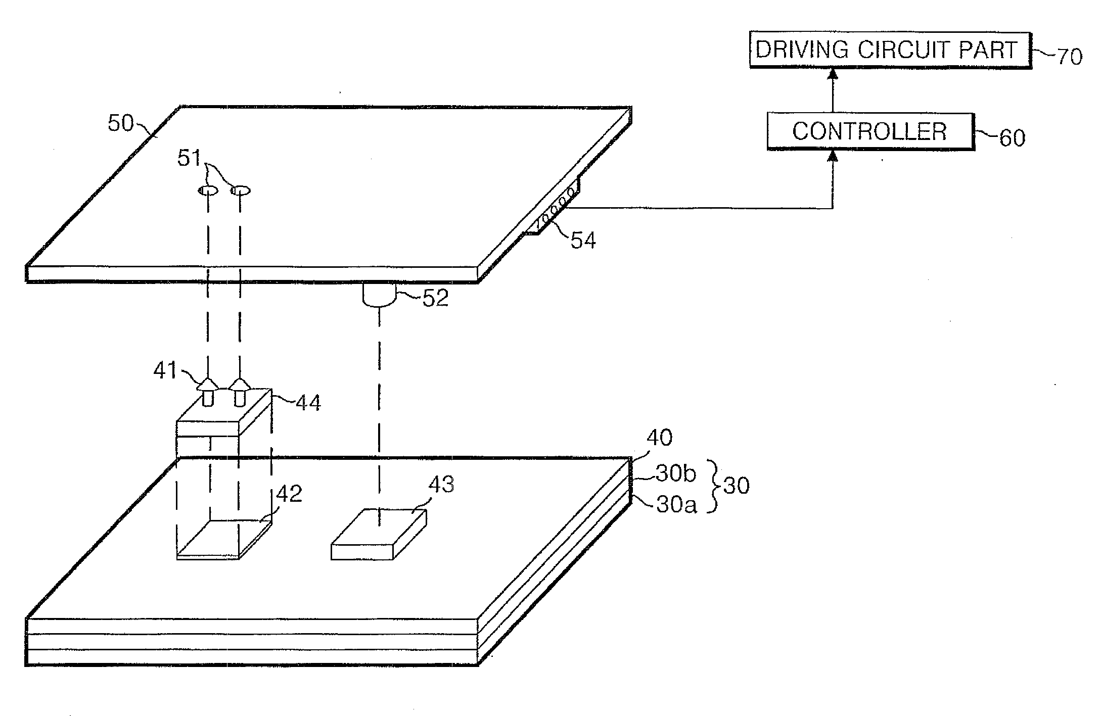
[0047]FIG. 5 is a configuration of an apparatus of driving a plasma display panel according to an embodiment of the present invention, and FIG. 6 is a configuration of the plasma display panel shown in FIG. 5 rotated by 180°.

[0048]Referring to FIGS. 5 and 6, a PDP according to the present invention includes: a panel 30; a heat-proof plate 40, attached on a rear surface of the panel 30, for dissipating a heat generated upon driving the panel 30; a sensor PCB 50 having a temperature sensor 50 installed thereon for detecting a temperature of the panel 30; a controller 60 for producing different control signals in accordance with the temperature of the panel detected by the sensor PCB 50; and a driving ...


PUM


Abstract

A temperature of the plasma display panel is detected by a temperature sensor. An apparatus includes a display panel, a plate disposed adjacent to a rear surface of the panel, and a board disposed substantially parallel to the plate. A temperature sensor is formed on the board, and the temperature sensor is disposed between the plate and the board.

Description

CROSS-REFERENCE TO RELATED APPLICATIONS[0001]This application is a Continuation application of prior U.S. patent application Ser. No. 10 / 849,875 filed May 21, 2004, which claims priority under 35 U.S.C. §119 to Korean Application No. P2003-33075 filed on May 23, 2003, whose entire disclosures are hereby incorporated by reference.BACKGROUND[0002]1. Field of the Invention[0003]The present invention relates to a plasma display panel, and more particularly, to an apparatus of driving a plasma display panel capable of accurately detecting a temperature of the plasma display panel for a stable driving of the plasma display panel.[0004]2. Description of the Related Art[0005]Recently, various flat panel devices have been developed that reduce weight and bulk, which are drawbacks of the cathode ray tube (CRT). Such flat panel display devices include a liquid crystal display (LCD) device, a field emission display (FED) device, a plasma display panel (PDP), an electro-luminescence display (ELD...

Claims


Application Information

Patent Timeline
IPC IPC(8): G09G3/28H01J17/28H01J17/49H05K1/02
CPCG09G3/28G09G2320/041H05K5/02H05K1/0201H01J2217/492G09G2310/066G09G3/2927G09G3/293H01J17/28G09G3/296
Inventor KONG, JUN HEEPARK, KI DUCK
Owner LG ELECTRONICS INC
Learn More