
Internal noise reducing structures in camera systems employing an optics stack and associated methods

a technology of optics stack and internal noise reduction, which is applied in the field of camera systems, can solve the problems of increasing noise, reducing not being practicable to make the spacer substrate out of a non-reflective material, so as to reduce the amount of light entering, reduce the amount of noise, and reduce the crosstalk between detectors

Inactive Publication Date: 2008-06-12
DIGITALOPTICS CORPORATION
View PDF9 Cites 37 Cited by
  • Summary
  • Abstract
  • Description
  • Claims
  • Application Information

AI Technical Summary

Benefits of technology

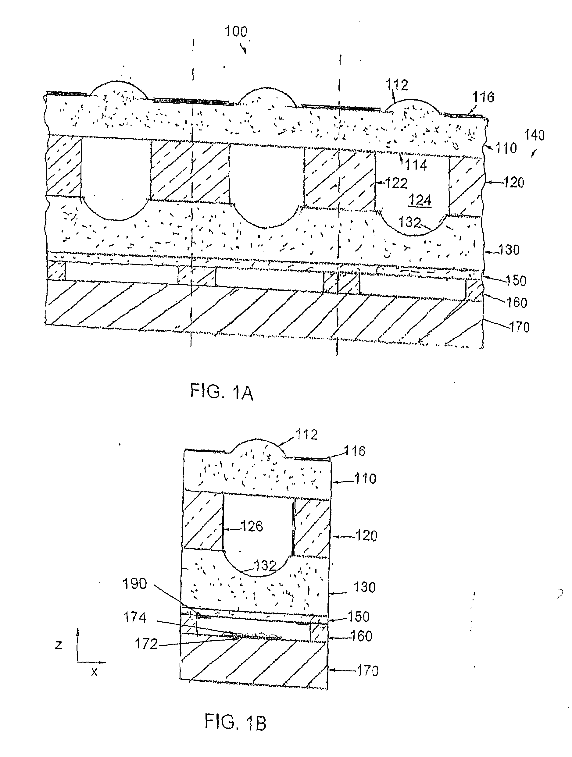
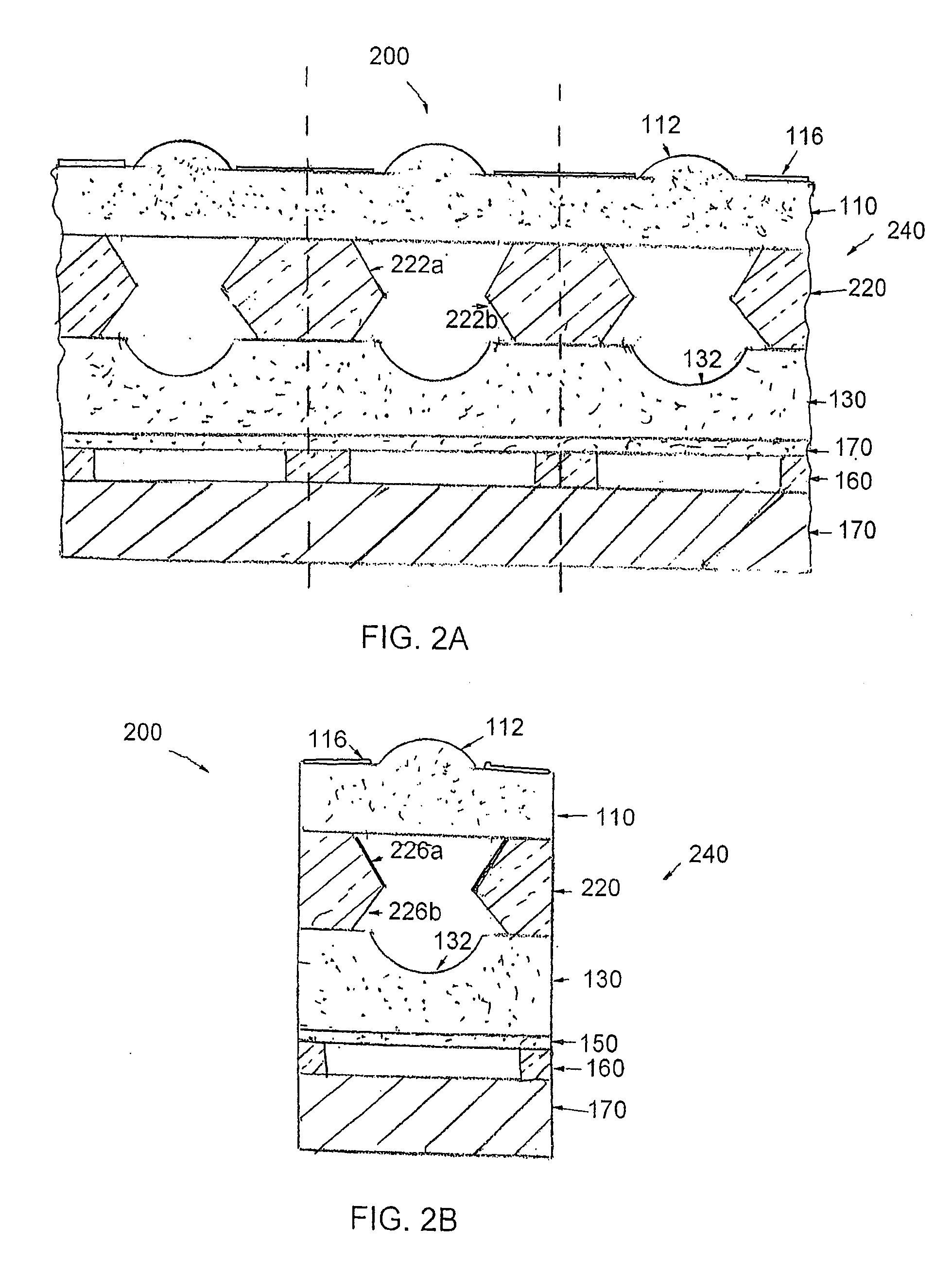
"The present invention provides a camera system with an optics stack and associated methods that overcome the limitations and disadvantages of related art. The invention includes features such as reducing noise from reaching the detector of the camera system, reducing crosstalk between detectors of the camera system, and improving image quality. The optics stack includes at least first, second, and third substrates stacked in a stacking direction, with the second substrate being formed of an optically absorbing material. The invention also provides a method of forming an inchoate optical module by providing a patterned optically absorbing material in a solid form on a first substrate, and adding a third substrate with at least one optical feature on the second substrate to form the optics stack."

Problems solved by technology

Depending on where sidewalls of the air gaps in the spacer substrate are located in the optics stack, they may aid in directing unwanted light onto the detector due to reflection off the sidewall, increasing noise.
However, it may not be practical to make the spacer substrate out of a non-reflective material.
While it may be sufficient to create a conventional housing simply out of an opaque material, opaque materials may still reflect light, which, for structures internal to the camera system, is undesirable.
Further, when the optics stack includes an array of lens systems, e.g., more than one lens on at least one surface of the optics stack, each for imaging light onto a corresponding active area in the detector, even light that is properly part of an image is incident on one active area detector may give rise to crosstalk when incident on another active area, increasing noise.

Method used


Image

  • Internal noise reducing structures in camera systems employing an optics stack and associated methods
  • Internal noise reducing structures in camera systems employing an optics stack and associated methods
  • Internal noise reducing structures in camera systems employing an optics stack and associated methods

Examples


Embodiment Construction

[0034]The present invention will now be described more fully hereinafter with reference to the accompanying drawings, in which preferred embodiments of the invention are shown. The invention may, however, be embodied in different forms and should not be construed as limited to the embodiments set forth herein. Rather, these embodiments are provided so that this disclosure will be thorough and complete, and will fully convey the concept of the invention to those skilled in the art.

[0035]In the drawings, the thickness of layers and regions may be exaggerated for clarity. It will also be understood that when a layer is referred to as being “on” another layer or substrate, it may be directly on the other layer or substrate, or intervening layers may also be present. Further, it will be understood that when a layer is referred to as being “under” another layer, it may be directly under, or one or more intervening layers may also be present. In addition, it will also be understood that wh...


PUM


Abstract

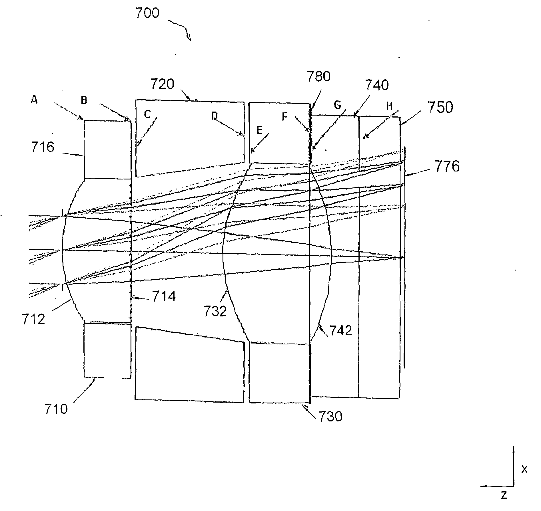
A camera system may include an optics stack including first and second substrates secured together in a stacking direction, one of the first and seconds substrates including an optical element, a detector on a sensor substrate, and a feature reducing an amount of light entering at an angle greater than a field of view of the camera system from reaching the detector, the feature being on another of the first and second substrates.

Description

CROSS REFERENCE TO RELATED APPLICATION(S)[0001]This application is related to provisional application Ser. No. 60 / 859,519, filed Nov. 17, 2006, the entire contents of which is hereby incorporated by reference.1. FIELD OF THE INVENTION[0002]The present invention is directed to a camera system and associated methods. More particularly, the present invention is directed to a camera system including internal structures for reducing noise, and associated methods.2. BACKGROUND OF THE INVENTION[0003]Cameras may include an optics stack of optical substrates secured to one another at planar portions thereof. A plurality of these optics stacks may be made simultaneously, e.g., at a wafer level.[0004]Further, since the optical system may be formed of a vertical stack of substrates secured to one another, it may be that a housing for mounting lenses in the optical system, e.g., a barrel, could be eliminated. In order to provide appropriate spacing, including air gaps, between the substrates, st...

Claims


Application Information

Patent Timeline
Patent Type & Authority Applications(United States)
IPC IPC(8): H04N5/225
CPCH01L27/14618H01L27/14623H01L27/14627H04N5/2257H01L27/14685H01L27/1469H04N5/2254H01L27/14634H01L2924/0002H04N23/57H01L2924/00H01L27/146G03B17/00H04N23/00
Inventor MORRIS, JAMESTEKOLSTE, ROBERTHAN, HONGTAOKINTZ, GREGELLIOT, PAULCLASSEY, JEFFMORRIS, KATHERINENYSTROM, MICHAEL
Owner DIGITALOPTICS CORPORATION
Learn More