Liquid crystal display having common and floating electrodes on one of substrates thereof

a technology of liquid crystal display and floating electrode, which is applied in non-linear optics, instruments, optics, etc., can solve the problems of increased cost of tn mode lcd, inability to eliminate hereditary drawbacks, and narrow viewing angles

Active Publication Date: 2008-06-12
INNOLUX CORP
View PDF13 Cites 43 Cited by
  • Summary
  • Abstract
  • Description
  • Claims
  • Application Information

AI Technical Summary

Problems solved by technology

Even though TN mode LCDs have been put into use in many applications, they have an inherent drawback that cannot be eliminated; namely, a very narrow viewing angle.
However, the cost of the TN mode LCD is increased.

Method used


Image

  • Liquid crystal display having common and floating electrodes on one of substrates thereof
  • Liquid crystal display having common and floating electrodes on one of substrates thereof
  • Liquid crystal display having common and floating electrodes on one of substrates thereof

Examples


first embodiment

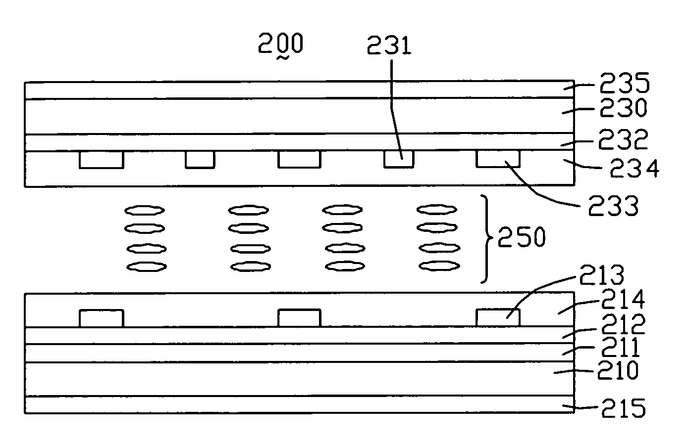
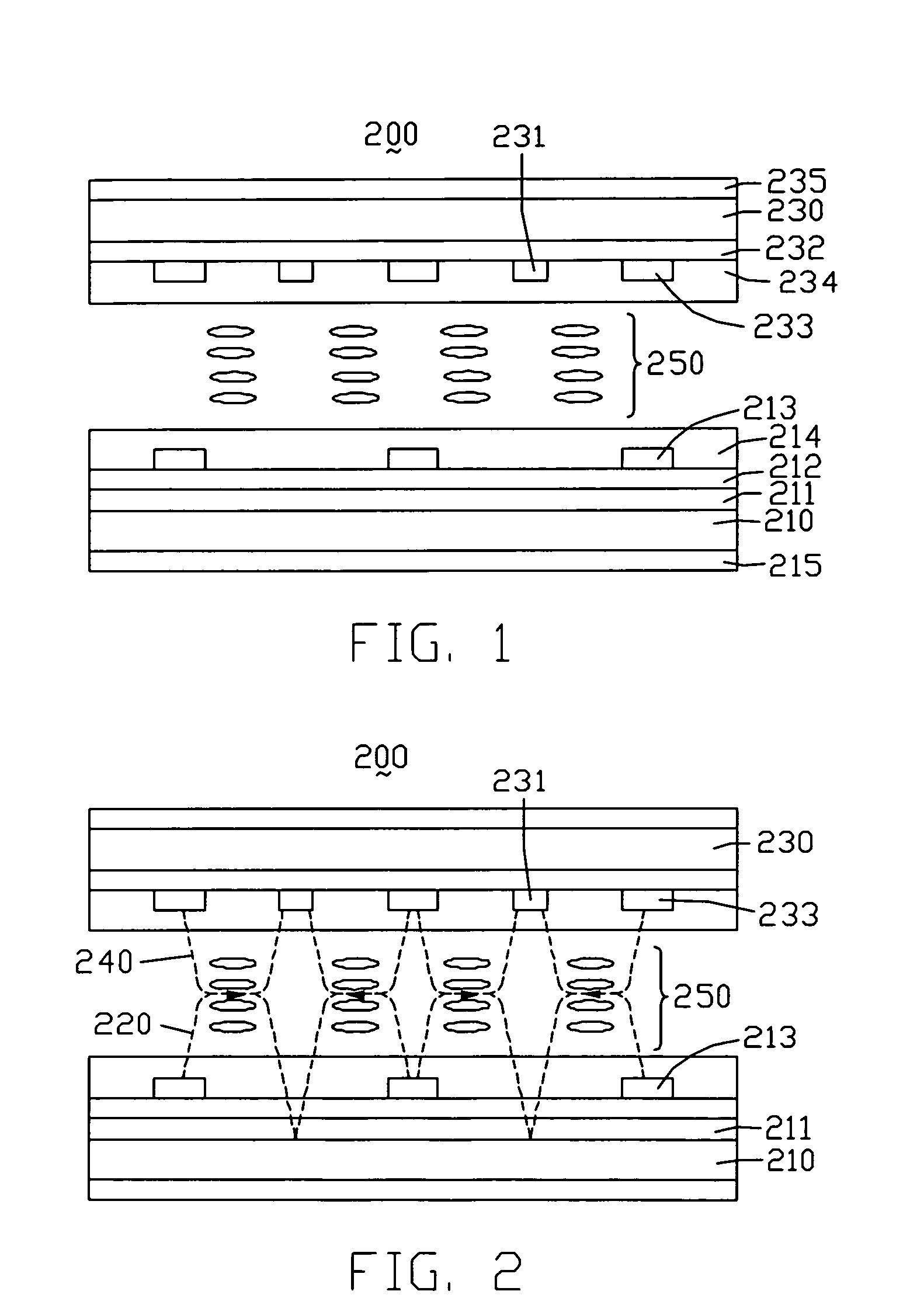
[0023]Referring to FIG. 1 and FIG. 2, an FFS LCD 200 according to the present invention is shown. The FFS LCD 200 includes a first substrate 210, a second substrate 230 opposite and parallel to the first substrate 210, a liquid crystal layer 250 sandwiched between the first and second substrates 210, 230. The first and second substrates 210, 230 are made from a transparent material, such as glass or quartz. The liquid crystal layer 230 includes a plurality of nematic-type liquid crystal molecules.

[0024]The FFS LCD 100 further includes a first common electrode 211 formed at an inner surface of the first substrate 210 facing the liquid crystal layer 250, an insulating layer 212 covering the first common electrode 211, a plurality of pixel electrodes 213 formed on the insulating layer 212, a first alignment layer 214 covering the pixel electrodes 213, and a first polarizer 215 formed at an outer surface of the first substrate 210 far from the liquid crystal layer 250.

[0025]The FFS LCD ...

second embodiment

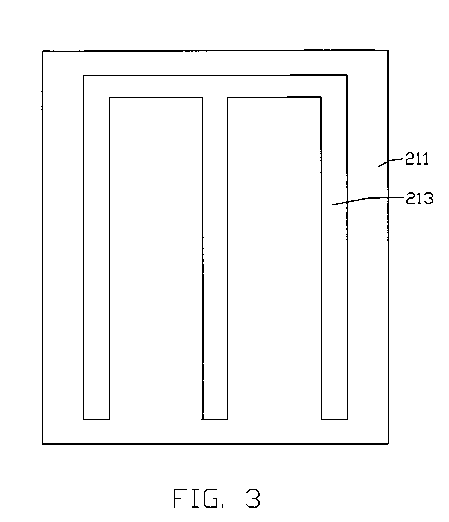
[0030]FIG. 5 shows pixel electrodes 313 of an LCD according to the present invention. The pixel electrodes 313 are comb-shaped, and include a plurality of wavy-shaped teeth electrodes extending from a straight bus line.

[0031]FIG. 6 shows floating electrodes 333 and second common electrodes 331 of an LCD according to a second embodiment of the present invention. The floating electrodes 333 and the second common electrodes 331 are comb-shaped, and include a plurality of wavy-shaped teeth electrodes extending from a straight bus line.

third embodiment

[0032]FIG. 7 shows pixel electrodes 413 of an LCD according to the present invention. The pixel electrodes 413 are comb-shaped, and include a plurality of rectilinearly bent or generally zigzag-shaped teeth electrodes extending from a straight bus line.

[0033]FIG. 8 shows floating electrodes 433 and second common electrodes 431 of an LCD according to a third embodiment of the present invention. The floating electrodes 433 and the second common electrodes 431 are comb-shaped, and include a plurality of rectilinearly bent or generally zigzag-shaped teeth electrodes extending from a straight bus line.

[0034]In an alternative embodiment, the second common electrodes 231 are plane-shaped, and are insulated from the pixel electrodes 233 by a second insulating layer sandwiched therebetween. The liquid crystal layer 230 can includes a plurality of liquid crystal molecules having negative dielectric anisotropy, and rubbing directions of the first and second alignment layer 214, 234 need to be ...


PUM

PropertyMeasurementUnit
electric fieldaaaaaaaaaa
transparentaaaaaaaaaa
opticalaaaaaaaaaa

Abstract

An exemplary liquid crystal display (LCD) (200) includes a first substrate (210); a second substrate (230) opposite to the first substrate; a liquid crystal layer (250) sandwiched between the first substrate and the second substrate; a first common electrode (211), a first insulating layer (212), and pixel electrodes provided at an inner surface of the first substrate in that order; and second common electrodes (231) and floating electrodes (233) provided at the second substrate. The first common electrode and the pixel electrodes, and the second common electrodes and the floating electrodes, respectively produce two electric fields in the liquid crystal layer corresponding to each other. A combined electric field strength is uniformly distributed in the liquid crystal layer, so that all the liquid crystal molecules can be sufficiently twisted. Thus a viewing angle, a degree of chroma, and a transmission ratio of the LCD are improved.

Description

FIELD OF THE INVENTION[0001]The present invention relates to liquid crystal displays, and particularly to a liquid crystal display having a plurality of common and floating electrodes on one of substrates thereof.GENERAL BACKGROUND[0002]A liquid crystal display (LCD) utilizes the optical and electrical anisotropy of liquid crystal molecules to produce an image. The liquid crystal molecules have a particular passive orientation when no voltage is applied thereto. However, in a driven state, the liquid crystal molecules change their orientation according to the strength and direction of the driving electric field. A polarization state of incident light changes when the light transmits through the liquid crystal molecules, due to the optical anisotropy of the liquid crystal molecules. The extent of the change depends on the orientation of the liquid crystal molecules. Thus, by properly controlling the driving electric field, an orientation of the liquid crystal molecules is changed and...

Claims


Application Information

Patent Timeline
Patent Type & Authority Applications(United States)
IPC IPC(8): G02F1/1343
CPCG02F1/134363G02F2201/124G02F2001/134372G02F2001/134318G02F1/134318G02F1/134372
Inventor LIN, YU-CHENGCHI, CHUN-YUNGCHEN, CHUEH-JU
Owner INNOLUX CORP
Why Eureka
Try Eureka