Liquid crystal display and electronic apparatus having a quasi-isotropic liquid crystal material

a liquid crystal display and electronic equipment technology, applied in the direction of optics, instruments, non-linear optics, etc., can solve the problems of reducing affecting the reliability and durability of the entire liquid crystal display, and the effect of high reliability

Active Publication Date: 2008-09-02
BOE TECH GRP CO LTD
View PDF13 Cites 36 Cited by
  • Summary
  • Abstract
  • Description
  • Claims
  • Application Information

AI Technical Summary

Benefits of technology

[0019]An advantage of the present invention is to provide a semi-transparent reflective liquid crystal display with high reliability that can achieve high visibility both in a bright environment and in a dark environment and to provide an electronic apparatus having the liquid crystal display.
[0020]The advantage is achieved in the present invention, as will be described below.
[0021]A first aspect of the invention is to provide a transflective liquid crystal display that, having a liquid crystal layer interposed between a pair of substrates facing each other, has a transparent display area for transparent display and a reflective display area for reflective display within a single pixel area. The liquid crystal layer is composed of a quasi-isotropic liquid crystal material that is optically isotropic when the non-selected electric field is applied and is optically anisotropic when the selected electric field is applied, the flexibility of which changing according to the electric field intensity. Here, the electric field intensity is supposed to be set smaller in the reflective display area than in the transparent display area.
[0022]Thus, high visibility can be achieved both in a bright environment and in a dark environment, which makes it possible to provide a semi-transparent reflective liquid crystal display with high reliability.
[0023]It is preferable in the liquid crystal display according to the first aspect of the invention that an selected electric field is applied in a direction almost parallel to the surface direction of the substrates.
[0024]Thus, a semi-transparent reflective liquid crystal display that has good visibility in all directions (with a wide viewing angle) can be provided.

Problems solved by technology

However, having a resin layer (a terraced part), such as described above, has resulted in problems, such as mentioned below.
Light will not be reflected efficiently on such an inclined plane.
There is also a problem that contrast is easily lowered due to decrease in the intensity of output light or to reflection (or transmission) of unnecessary light.
In such a case, however, the angle of the angled part, shown as E in the drawing, becomes so small (less than 90 degrees) that the adhesiveness of the phase contrast layer 200, the pixel electrode 230, the alignment layer 240 and the like may be drastically degraded, which causes degradation of the reliability and the durability of the entire liquid crystal display.
Further, a resin layer, such as described above, produces dead space, which is disadvantageous in terms of making devices thinner.
There also has been a problem that the liquid crystal alignment is disrupted at the terraced part on the boundaries, which causes degradation of the optical properties.
There also has been another problem that the viewing angle is narrow in a semi-transmissive reflective liquid crystal display.

Method used


Image

  • Liquid crystal display and electronic apparatus having a quasi-isotropic liquid crystal material
  • Liquid crystal display and electronic apparatus having a quasi-isotropic liquid crystal material
  • Liquid crystal display and electronic apparatus having a quasi-isotropic liquid crystal material

Examples


embodiments

[0131]Making of Liquid Crystal Material

[0132]The photo polymerization monomers used in the embodiments include non-liquid crystal 2-ethylhexyl acrylate (2EHA, Aldrich), hexyl acrylate (HA, Aldrich) and 1,3,3-trimethylhexyl acrylate (TMHA, Aldrich), and liquid crystal 6-(4′-cyanobiphenyl-4-yloxy)hexylacrylate (6CBA). A liquid crystal diacrylate monomer (RM257, Merck) is used as a crosslinking agent. 2,2-dimethoxy-2-phenylacetophenone (Aldrich) is used as a photo polymerization initiator. An equimolar mixture of a fluorochemical nematic liquid crystal mixture (JC-1041XX(7), Chisso) and a cyanobiphenyl nematic liquid crystal mixture 4-cyano 4′-pentyl biphenyl (5CB, Aldrich) is used as a low molecular weight liquid crystal material. ZLI-4572(9) (Merck) is used as a chiral dopant.

[0133]The mixed liquid solution in which the above-mentioned components are blended in a predetermined composition is filled into cells in a sandwich shape with a cell thickness of 14 μm, without orientation and...

embodiment example 1

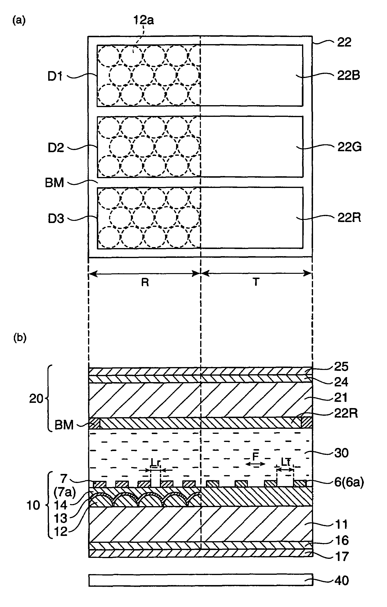
[0134]A liquid crystal display having a multigap structure just like the liquid crystal display shown in FIG. 2 is created using a quasi-isotropic liquid crystal material obtained in the above-mentioned process.

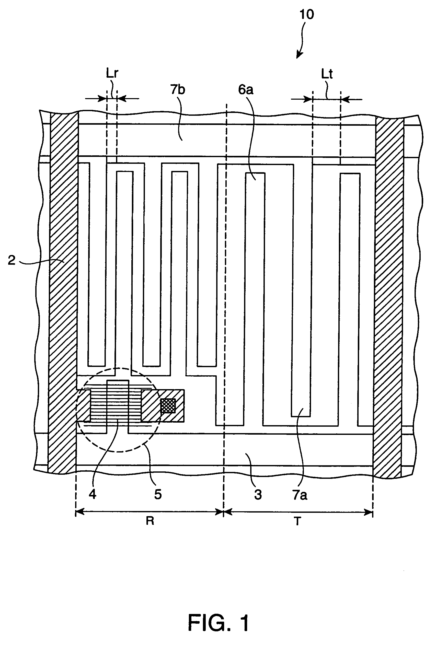
[0135]In the process, the phase contrast of a liquid crystal layer is set to satisfy the equation Δnd=270 nm (λ / 2). The absorption axis of the polarizing plate is set in the direction corresponding to an angle of 45 degrees from the longitudinal direction of the transparent electrode. The width of the electrode finger is set to be 2 μm, the distance between the electrodes on the transparent display area is set to be 10 μm, and the distance between the electrodes on the reflective display area is set to be 5 μm.

[0136]Then, the transmittance in the transparent display area and the reflectance on the reflective display area are measured while applying voltage from 0 to 5 V on the liquid crystal display. As a result, it turned out that the transmittance and the reflectance are bo...

embodiment example 2

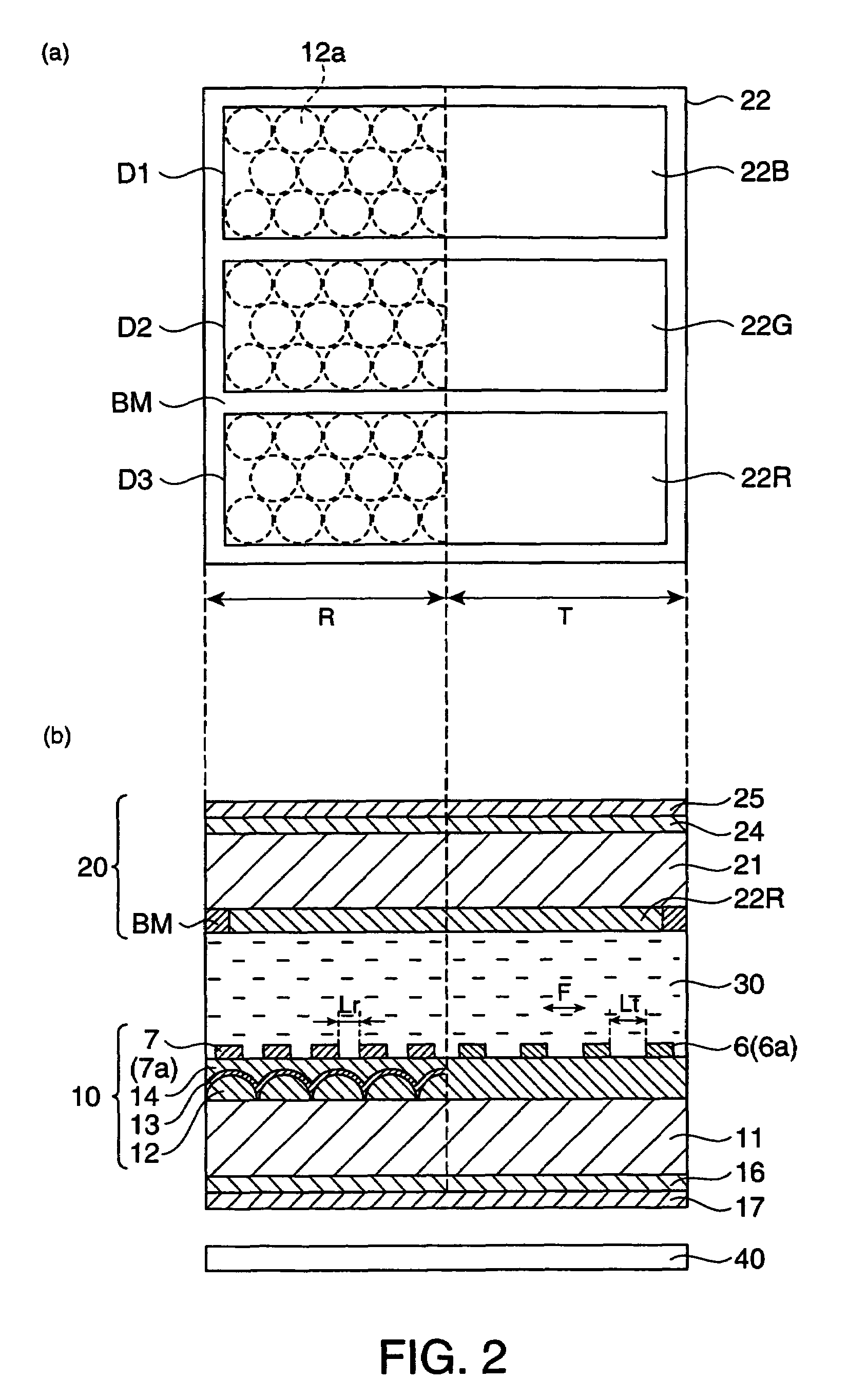
[0137]A liquid crystal display having a multigap structure just like the liquid crystal display shown in FIG. 3 is created using a quasi-isotropic liquid crystal material obtained in the above-mentioned process.

[0138]In the process, the phase contrast of a liquid crystal layer is set to satisfy the equation Δnd=140 nm (λ / 2). The absorption axis of the polarizing plate is set to be parallel in the longitudinal direction of the transparent electrode. The phase contrast plate is placed to an angle of 15 degrees from the longitudinal direction. The electrode finger is set to be 2 μm, the distance between the electrodes on the transparent display unit is set to be 4 μm, and the distance between the electrodes on the reflective display unit is set to be 8 μm.

[0139]Then, the transmittance in the transparent display area and the reflectance on the reflective display area are measured while applying voltage from 0 to 5 V on the liquid crystal display. As a result, it turned out that the tran...


PUM

PropertyMeasurementUnit
sizeaaaaaaaaaa
widthaaaaaaaaaa
widthaaaaaaaaaa

Abstract

A transflective liquid crystal display that includes a liquid crystal layer interposed between a pair of substrates facing each other and a transparent display area for transparent display and a reflecting display area for reflecting display within a single pixel area, wherein the liquid crystal layer is composed of a quasi-isotropic liquid crystal material that is optically isotropic when non-selected electric field is applied and is optically anisotropic when selected electric field is applied, the flexibility of which changing according to the electric field intensity, and the electric field intensity is supposed to be set smaller in the reflecting display area than in the transparent display area.

Description

BACKGROUND[0001]1. Technical Field[0002]The present invention relates to a liquid crystal display and an electronic apparatus.[0003]2. Related Art[0004]Liquid crystal displays (transflective liquid crystal displays) that utilize external light in bright places in a manner similar to that of normal reflective liquid crystal displays and make the display visible with an internal light source in dark places have been proposed. Such a liquid crystal display uses a display system that is both reflective and transparent to achieve a clear display even in darkness as well as to lower power consumption by switching the display mode between the reflection mode and the transparent mode according to the surrounding brightness.[0005]It is considered preferable that a transflective liquid crystal display has a multigap structure such as shown in JP-A-2004-219553 to effectively carry out reflective display and transparent display.[0006]A semi-transmissive reflective liquid crystal display having ...

Claims


Application Information

Patent Timeline
Patent Type & Authority Patents(United States)
IPC IPC(8): G02F1/1335G02F1/1343
CPCG02F1/1393G02F1/133555G02F2001/13345G02F1/13345G02F1/1335
Inventor OZAWA, KINYA
Owner BOE TECH GRP CO LTD
Why Eureka
Try Eureka