
Motor control center with power and data distribution bus

a technology of motor control center and power distribution bus, which is applied in the direction of instruments, non-enclosed substations, substations, etc., can solve the problems of increasing installation and maintenance costs, crowded wire passages within the mcc, and adding to the installation and maintenance costs of the system

Inactive Publication Date: 2008-06-12
ROCKWELL AUTOMATION TECH
View PDF40 Cites 79 Cited by
  • Summary
  • Abstract
  • Description
  • Claims
  • Application Information

AI Technical Summary

Benefits of technology

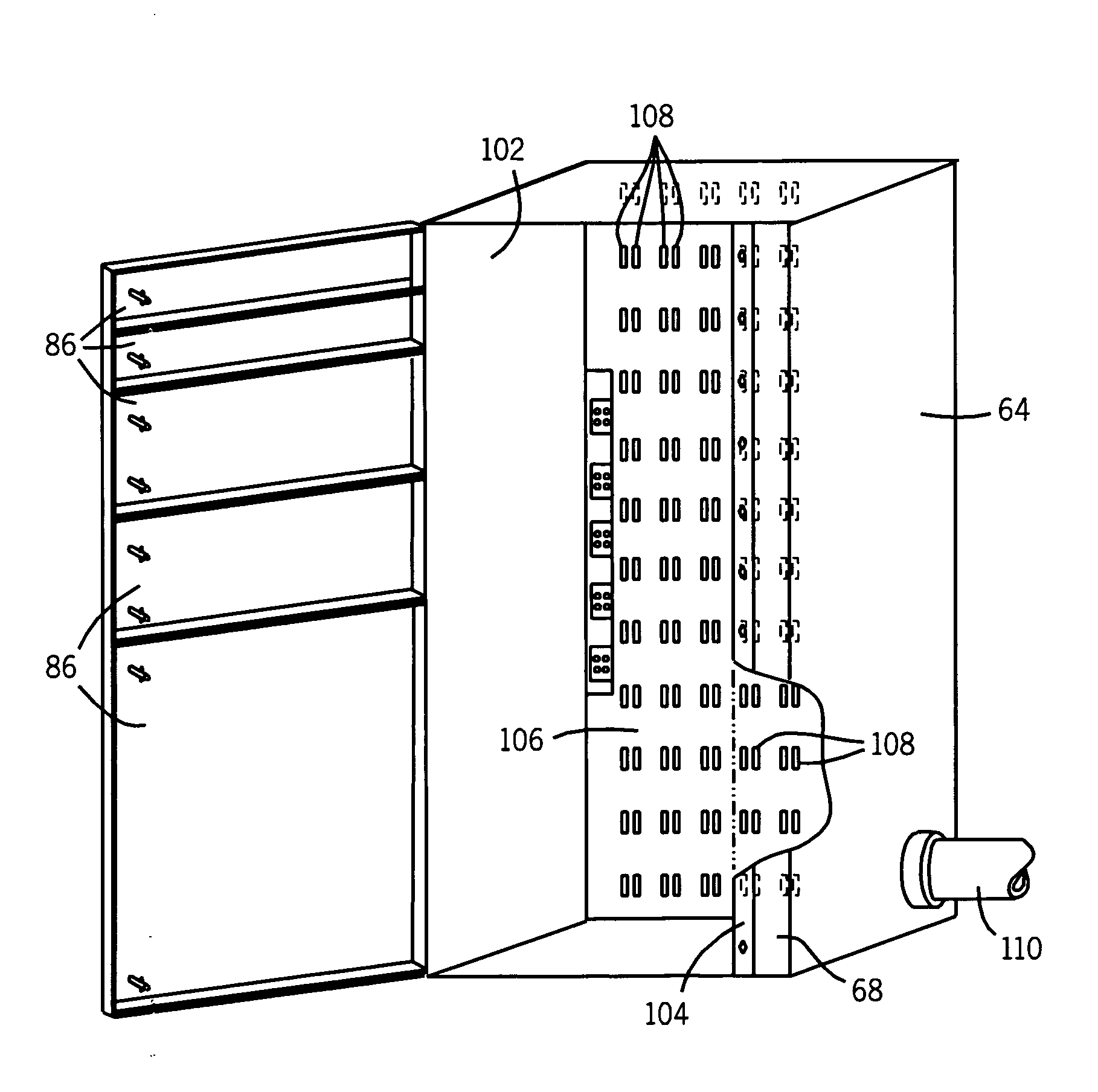
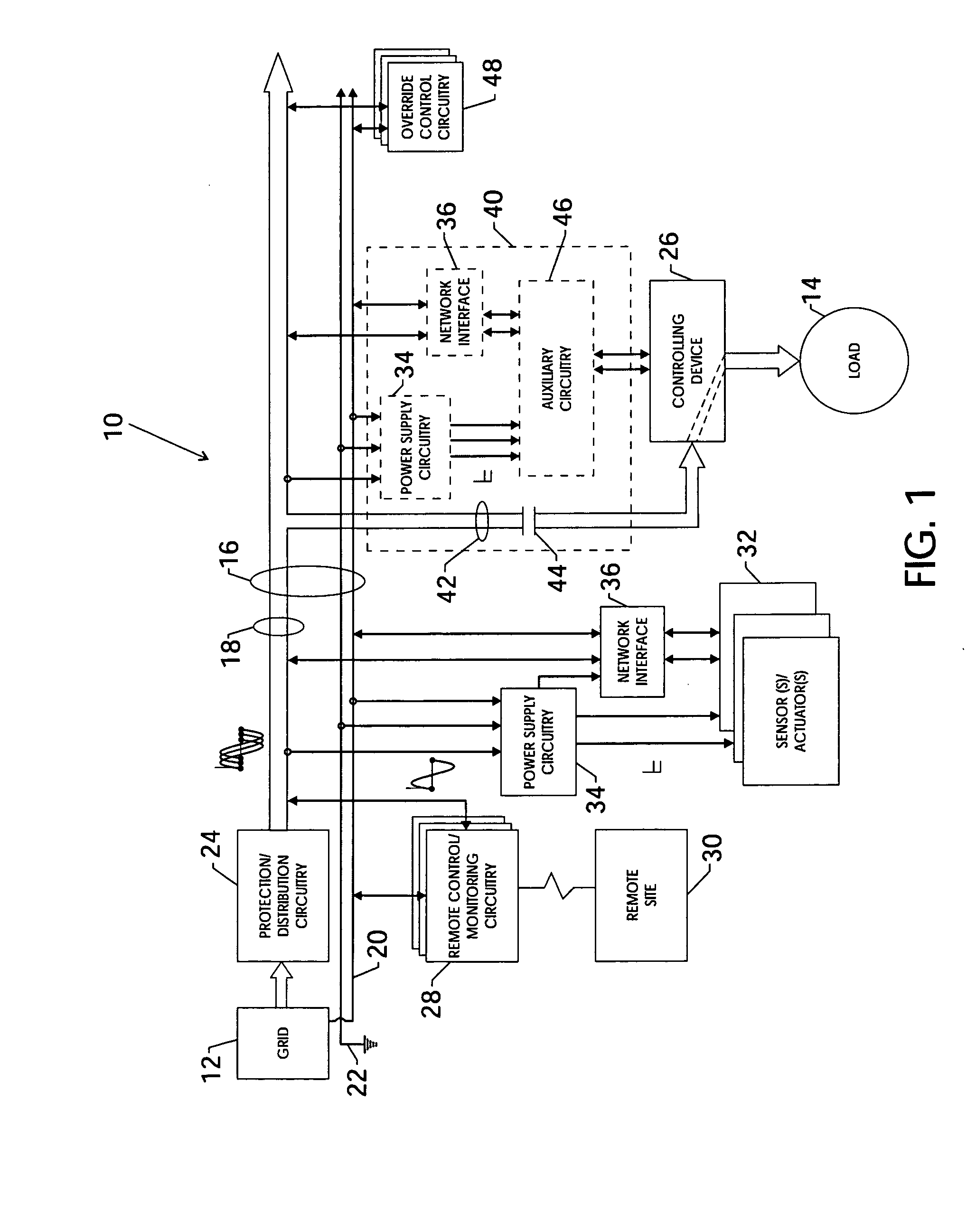
[0006]The present invention generally provides techniques for configuring an MCC and associated components to respond to the needs briefly outlined above. Particularly, the MCC utilizes a combined power and data distribution bus system comprising a plurality of conductive bus bars. The MCC and components are configured to concurrently transmit both power and data over the same conductive bus bars, thus avoiding the need for separate power distribution and data transmission systems. In one embodiment, the combined bus system concurrently transmits data signals and one phase of three-phase power over the same conductive path. In another embodiment, data signals are provided with auxiliary control power delivered by common auxiliary bus bars.

Problems solved by technology

In a typical MCC, the components are networked to each other via numerous wires, resulting in crowded wire passages within the MCC, and increased installation and maintenance costs.
Further, these network cables are often used to daisy-chain units to one another, preventing removal of a unit without first disconnecting the network cables, and further adding to installation and maintenance costs of the system.
However, this design generally requires installation of a discrete communication network within the MCC, and the application of low voltage dc power to operate the communication network.
Still further, such a network may impose certain hurdles on component design and selection to meet constraints of such a topology, including consideration of trunk length, drop budget, terminations, and data rate selections, to name but a few, which also impact manufacturing and servicing costs.

Method used


Image

  • Motor control center with power and data distribution bus
  • Motor control center with power and data distribution bus
  • Motor control center with power and data distribution bus

Examples


Embodiment Construction

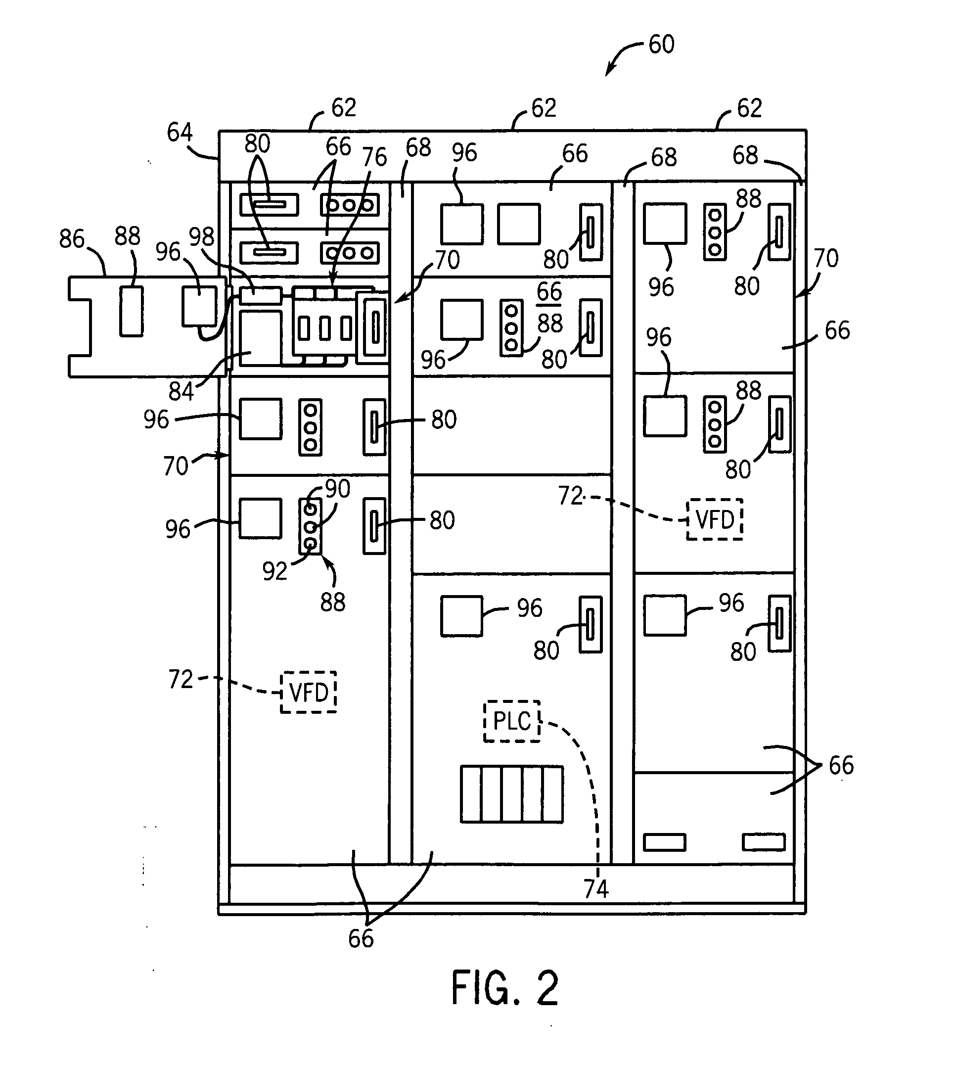
[0015]In industrial applications, efficient distribution of power and data signals is often a motivating concern. Referring to FIG. 1, an exemplary section of a power and data distribution system 10 is presented. Although, for the purposes of explanation, the present embodiment relates to an industrial application, the present technique can be applied to any number of settings in which the efficient distribution of power and data is a concern. Returning to the present embodiment, the power and data distribution system 10 comprises a three-phase power source 12, such as a generator or power grid. The three-phase power may be ac power, such as 480V power, that powers a load 14. For example, the load 14 may be a motor that operates on three-phase 480Vac power. For the present purposes, any voltage or current rating of ac power may be accommodated. Moreover, the power source 12 may be configured to provide other levels and kinds of power, such as 24Vdc, along with the primary three-phas...


PUM


Abstract

A motor control center (MCC) is provided. The MCC includes a power and data distribution bus comprising a plurality of conductive bars for distributing power and data signals within the MCC. In one embodiment, the plurality of conductive bars is configured to receive and distribute three-phase power from an external power source. The MCC may also include a device configured to receive power and data from the plurality of conductive bars. Devices and methods for distributing power and data to such devices within an MCC are also disclosed.

Description

BACKGROUND[0001]The present technique generally relates to power and data distribution within a motor control center (MCC). More particularly, the present technique relates to distribution of both power and data signals over a common power and data distribution bus.[0002]In a number of applications, networked systems require distribution of both power and data signals to and from any number of devices. For example, in industrial applications, a networked system may distribute power, typically three-phase power, as well as appropriate data signals to any number of locations and devices. In traditional systems, power and data signals are transmitted over discrete wiring pathways. That is, power is distributed over dedicated power wires and data is distributed over dedicated data wires, both of which are disposed in separate protective conduits or cable jackets tubing.[0003]As will be appreciated, an MCC may house a number of components of the industrial system, generally providing a c...

Claims


Application Information

Patent Timeline
IPC IPC(8): H02B5/00
CPCH02B1/21
Inventor JENSEN, DAVID L.BRANDT, DAVID D.
Owner ROCKWELL AUTOMATION TECH
Learn More