Fan module

Inactive Publication Date: 2008-06-12
AMA PRECISION INC
View PDF2 Cites 4 Cited by
  • Summary
  • Abstract
  • Description
  • Claims
  • Application Information

AI Technical Summary

Benefits of technology

[0010]Another objective of the invention is to provide a fan module to solve the problem that when a light source set or a blade set is damaged

Problems solved by technology

Therefore, the user is limited in choosing the fan efficiency (The heat dissipation efficiency of the fan module 100 cannot satisfy an electronic device with high heat emitting power).
Additionally, the design of disposing the light-emitting element 130 at the frame 110 directly easily increases the maintenance cost of the fan module 100.
For example, if the blade set is damaged and the light-emitting element can still work normally, the user cannot only replace the blade set bu

Method used


Image

  • Fan module
  • Fan module
  • Fan module

Examples


Example

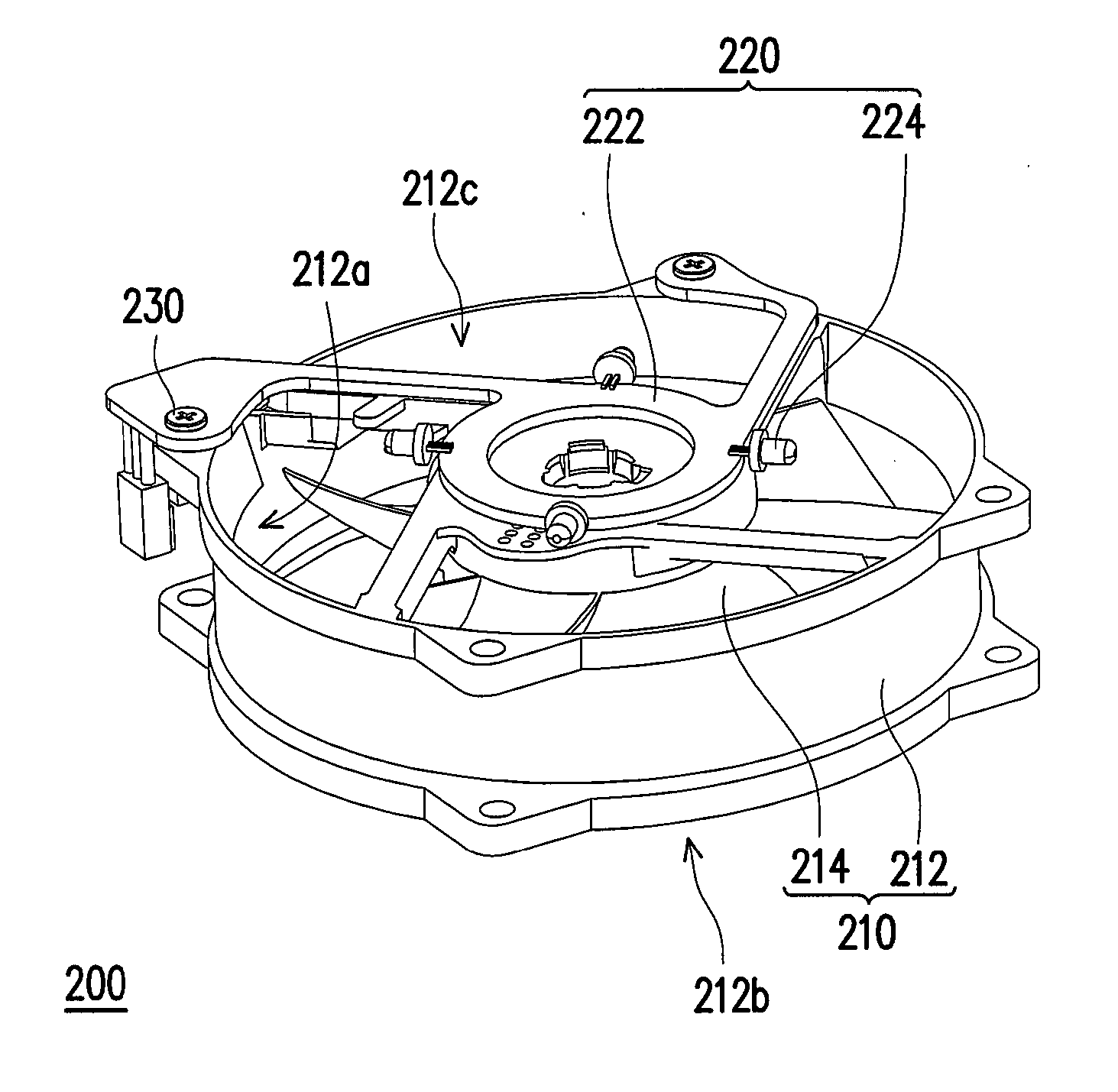
[0029]FIG. 2A is a three-dimensional schematic diagram showing a fan module in one preferred embodiment of the invention, and FIG. 2B is an exploded diagram showing the fan module in FIG. 2A. Please refer to FIG. 2A and FIG. 2B, and a fan module 200 in the embodiment includes a fan 210 and a light source set 220. In the embodiment, the fan 210 mostly includes a frame 212 and a blade set 214, and the frame 212 has a accommodating space 212a, an air inlet 212b, and an air outlet 212c. Wherein the blade set 214 is disposed in the accommodating space 212a, and the air inlet 212b and the air outlet 212c are communicated with each other. When the blade set 214 rotates, airflow is sucked from the air inlet 212b, and is exhausted from the air outlet 212c.

[0030]From the above, the light source set 220 in the embodiment is, for example, disposed on the frame 212 via a plurality of fasteners 230. For example, the frame 212 has a plurality of first fixing holes 212d, and the light source set 2...


PUM


Abstract

A fan module including a fan and a light source set is provided. The fan includes a frame and a blade set. The frame has a accommodating space, an air inlet and an air outlet, and the air inlet and the air outlet are communicated with each other. The blade set is provided at the accommodating space. The light source set is provided at the frame as an independent module and has a circuit board and a plurality of light-emitting elements provided at the circuit board. Another fan module including a blade set base, a light source set, and a support is provided, wherein the light source set is provided at the blade set base. The light source set includes a circuit board and at least one light-emitting elements provided at the circuit board, and the circuit board is disposed between the blade set base and the support.

Description

CROSS-REFERENCE TO RELATED APPLICATION[0001]This application claims the priority benefit of Taiwan application serial no. 95145595, filed on Dec. 7, 2006. The entirety of the above-mentioned patent application is hereby incorporated by reference herein and made a part of this specification.BACKGROUND OF THE INVENTION[0002]1. Field of the Invention[0003]The invention relates to a fan module and, more particularly, to a fan module with a light source set.[0004]2. Description of Related Art[0005]A fan is a needful element in electronic heat dissipation technology, and an electronic device can effectively decrease its interior working temperature via the convection effect between the active airflow generated by the fan and ambient environment. Additionally, modern fans further need to have unique models besides preferred heat dissipation efficiency, and then fans with light-emitting elements are developed.[0006]FIG. 1A is an exploded diagram showing a conventional fan module, and FIG. 1...

Claims


Application Information

Patent Timeline
IPC IPC(8): H05K7/20
CPCH05K7/20172
Inventor HU, SHAO-HUAHUANG, CHI-CHUN
Owner AMA PRECISION INC
Why Eureka
Try Eureka