
Bridged LAN and communication node therefor

a communication node and bridge technology, applied in the field of bridged lan, can solve the problems of difficult to construct a different spanning tree for each of the services in the transit network, and achieve the effect of high real-time property

Active Publication Date: 2008-06-12
HITACHI LTD
View PDF8 Cites 17 Cited by
  • Summary
  • Abstract
  • Description
  • Claims
  • Application Information

AI Technical Summary

Benefits of technology

[0025]An object of the present invention is to provide a bridged LAN which can construct spanning trees different for each of services in a transit network.
[0026]Another object of the present invention is to provide a communication node apparatus which can construct spanning trees different for each of services in the transit network of the bridged LAN.
[0038]According to the present invention, since a spanning tree can be formed in the transit network of a bridged LAN in accordance with the type of a service used by a network application, even though a plurality of data frames have the same VLAN identifier, data frames having a high real-time property can be forwarded through an optimized communication route different from a communication route for the other data frames. In addition, in a bridged LAN according to the present invention, it is also possible to make use of the advantage achieved by dividing the broadcast domain, which is a characteristic feature of the VLAN, and a broadcast-storm suppressing effect which is an advantage of the STP.

Problems solved by technology

In the MST, however, the STP is applied to each of the VLANs individually as described above and it is impossible to construct a different spanning tree for each of services in the transit network.
Thus, according to the existing MST, it is difficult to construct spanning trees different depending on a service type, such as WEB service or VoIP.

Method used


Image

  • Bridged LAN and communication node therefor
  • Bridged LAN and communication node therefor
  • Bridged LAN and communication node therefor

Examples


embodiment 1

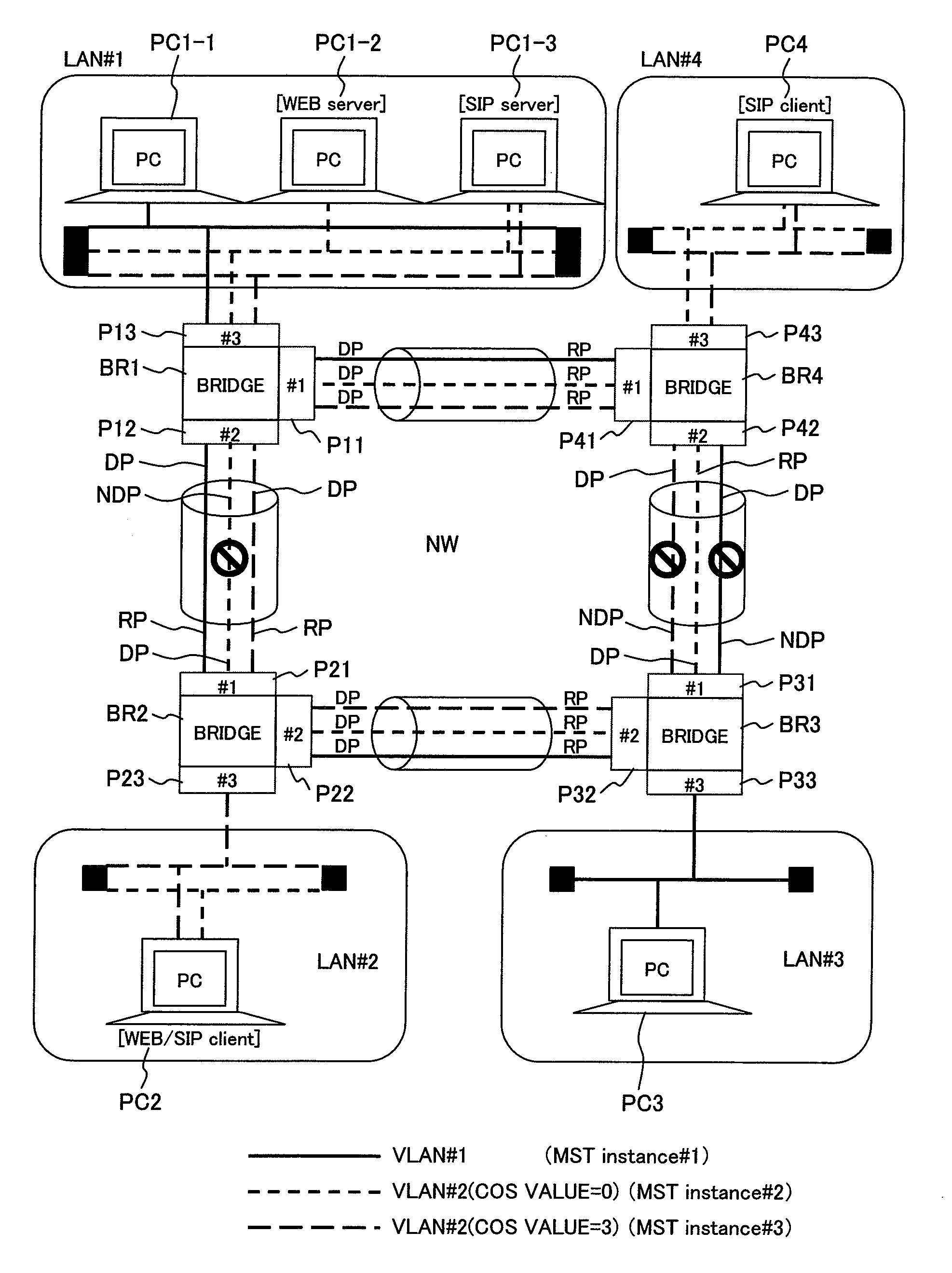
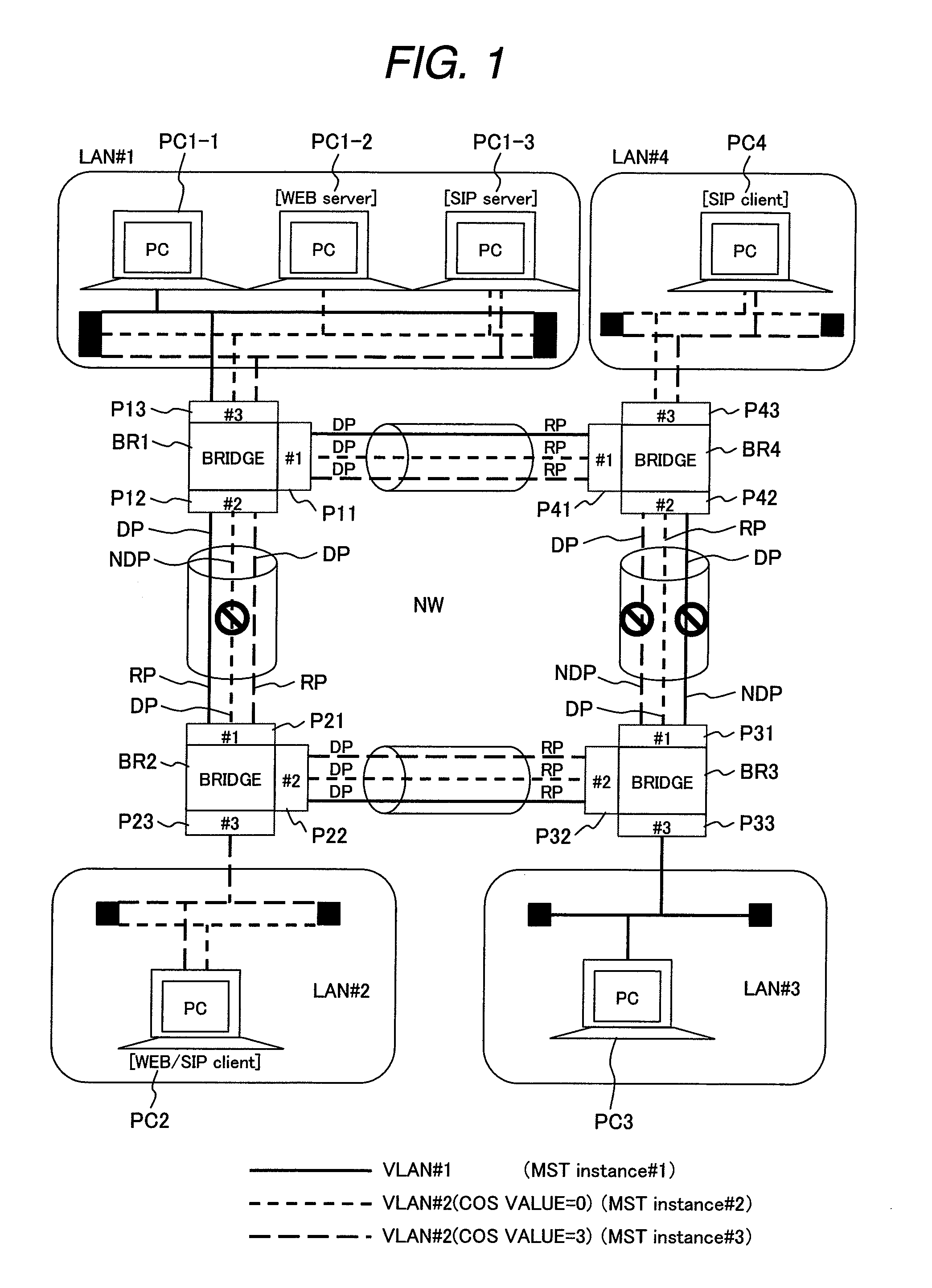
[0061]FIG. 1 shows an example of a network structure of a bridged VLAN to which the present invention is applied. The network shown here as an example includes LANs #1 to #4 and a transit network NW including bridges BR1 to BR4 connected in a loop-like shape. To the LANs #1 to #4, personal computers PC1-1 to PC1-3, PC2, PC3, and PC4 are connected, respectively, in the same manner as in FIG. 20.

[0062]In the bridged LAN shown in FIG. 1, two VLANS; a VLAN #1 indicated by the solid line and a VLAN #2 indicated by the broken line, are formed. In the same manner as in FIG. 20, the personal computer PC1-1 connected to the LAN #1 and the entire LAN #3 belong to the VLAN #1. The personal computers PC1-2 and P1-3 each connected to the LAN #1, the entire LAN #2, and the entire LAN #4 belong to the VLAN #2. In the VLAN #2, the personal computer PC1-2 functions as a WEB server, the personal computer PC1-3 functions as a SIP server, the personal computer PC2 is a client of WEB and SIP, and the pe...

embodiment 2

[0100]FIG. 12 shows an example of a structure of another network structure of the bridged VLAN to which the present invention is applied.

[0101]The network shown in FIG. 12 is different from that of FIG. 1 in that another LAN #5 is connected to the transit network NW via a gateway GW1. Although the gateway GW1 is connected to the transit network NW via the LAN #2 in FIG. 12, the gateway GW1 may be connected directly to the Ethernet port P23 of the bridge BR2.

[0102]The gateway GW1 is connected to the LAN #2 via an Ethernet port GP1 and connected to the LAN #5 via an Ethernet port GP2 to forward communication frames received from the LAN #5 to the LAN #2 and forward communication frames received from the LAN #2 to the LAN #5.

[0103]Upon receiving a communication frame from the LAN #5, the gateway GW1 according to the present embodiment specifies the COS value in accordance with the TCP / UDP port number indicated by the received frame, sets the specified COS value to the tag field of the ...


PUM


Abstract

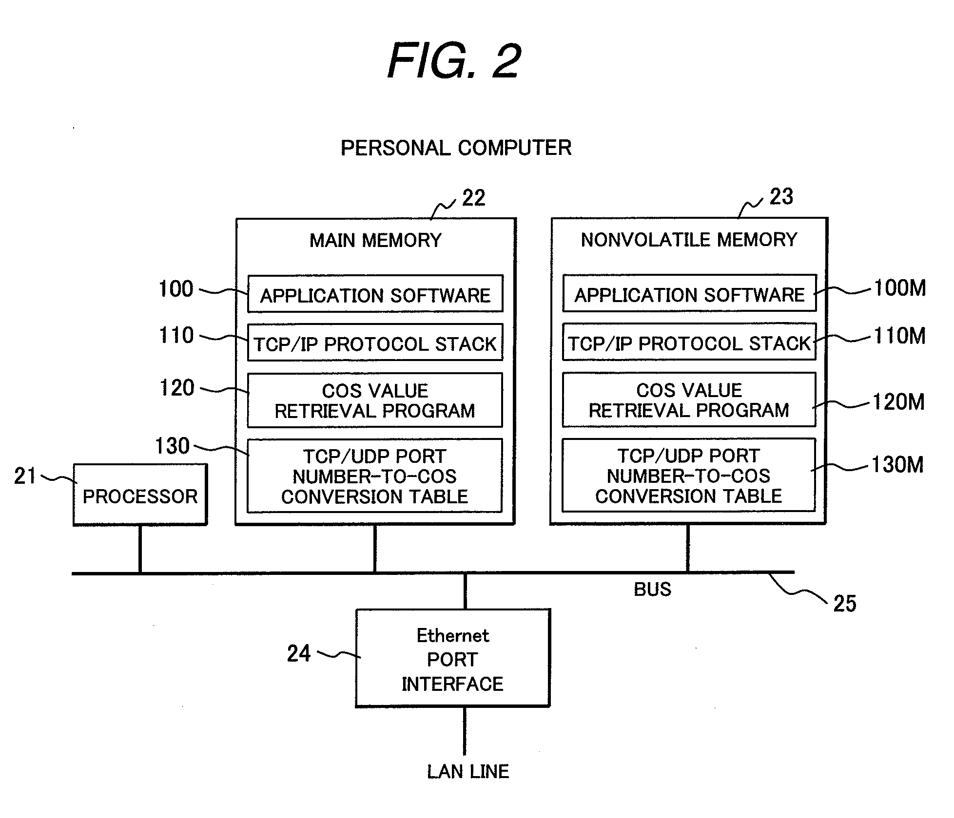
A spanning tree is formed for each of MST (Multiple Spanning Tree Protocol) instances defined by a VLAN ID and a COS value. Each terminal apparatus specifies the COS value corresponding to the TCP / UDP port number of a Ethernet frame to be transmitted, based on a conversion table indicating the correspondence of a TCP / UDP port number to a COS value and sets the specified COS value to the header of the Ethernet frame. Each of bridges in the transit network specifies the MST instance identifier of a received frame based on a conversion table indicating the correspondence of the MST instance identifier to the combination of a VLAN ID and a COS value and forwards the received frame in accordance with the spanning tree having the specified MST instance.

Description

CLAIM OF PRIORITY[0001]The present application claims priority from Japanese patent application serial No. 2006-330992, filed on Dec. 7, 2006, the content of which is hereby incorporated by reference into this application.BACKGROUND OF THE INVENTION[0002]1. Field of the Invention[0003]The present invention relates to a bridged LAN and, more particularly, to a bridged LAN (Local Area Networks) in which a spanning tree is applied to VLANs (Virtual LANs) and to a communication node apparatus, a terminal apparatus, and a gateway apparatus each applied to the bridged LAN.[0004]2. Description of the Related Art[0005]In recent years, there has been an increase in the number of network configurations each including a plurality of geometrically distributed intra-company LANs connected via a transit network, e.g., a public network. FIG. 18 shows an example of such a network configuration, in which LANs #A1 and #A2 in a company A are connected via a transit network NW. Likewise, LANs #B1 and #...

Claims


Application Information

Patent Timeline
IPC IPC(8): H04L12/28H04L12/44H04L12/46H04L45/18
CPCH04L12/462H04L12/4641H04L45/00H04L69/326H04L45/302H04L45/48H04L45/04H04L45/76
Inventor NOZUE, DAIKIMIYATA, HIROAKI
Owner HITACHI LTD
Learn More