System For Measuring And Indicating Changes In The Resistance Of A Living Body

a technology of resistance and living body, applied in the field of living body resistance measurement and indicating changes, can solve the problems of difficult calibration, difficult operation in a manner consistent with accurately perceived display readings, complicated the ability to obtain clear readings, etc., to improve display response and accuracy.

Active Publication Date: 2008-06-12
CHURCH OF SPIRITUAL TECH
View PDF18 Cites 19 Cited by
  • Summary
  • Abstract
  • Description
  • Claims
  • Application Information

AI Technical Summary

Benefits of technology

[0007]The invention herein is an improved device for measuring and indicating resistance and resistance changes in a living body. The device utilizes digital processing to improve display response and accuracy. An automatic calibration sequence substantially offsets the effects of component aging, temperature changes and manufacturing tolerances on these very sensitive measurements. Preferred circuitry for sensitivity adjustments isolates those adjustments from effecting the resistance measurement circuitry.

Problems solved by technology

While the foregoing prior art devices have been suitable for detecting the resistance changes in the living body, they have been difficult to calibrate correctly and difficult to operate in a manner that consistently produces accurately perceived display readings.
It appears that these difficulties arise from such characteristics as signal non-linearities, as well as age-related and temperature-related component changes that can mask or falsely report small but meaningful measurement changes.
Inventor Hubbard recognized that signal non-linearities were a significant factor that greatly complicated the reliable display of needed information, and that the interaction between range and sensitivity adjustments on such devices further complicated the ability to obtain clear readings. Mr. Hubbard further identified slight delays as small as 0.1 seconds in displaying resistance changes as a further source that complicated auditing and determined that the most effective display required even the smallest possible resistance changes to be perceived with as little delay as possible.

Method used


Image

  • System For Measuring And Indicating Changes In The Resistance Of A Living Body
  • System For Measuring And Indicating Changes In The Resistance Of A Living Body
  • System For Measuring And Indicating Changes In The Resistance Of A Living Body

Examples


Embodiment Construction

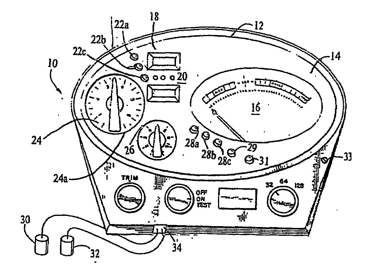
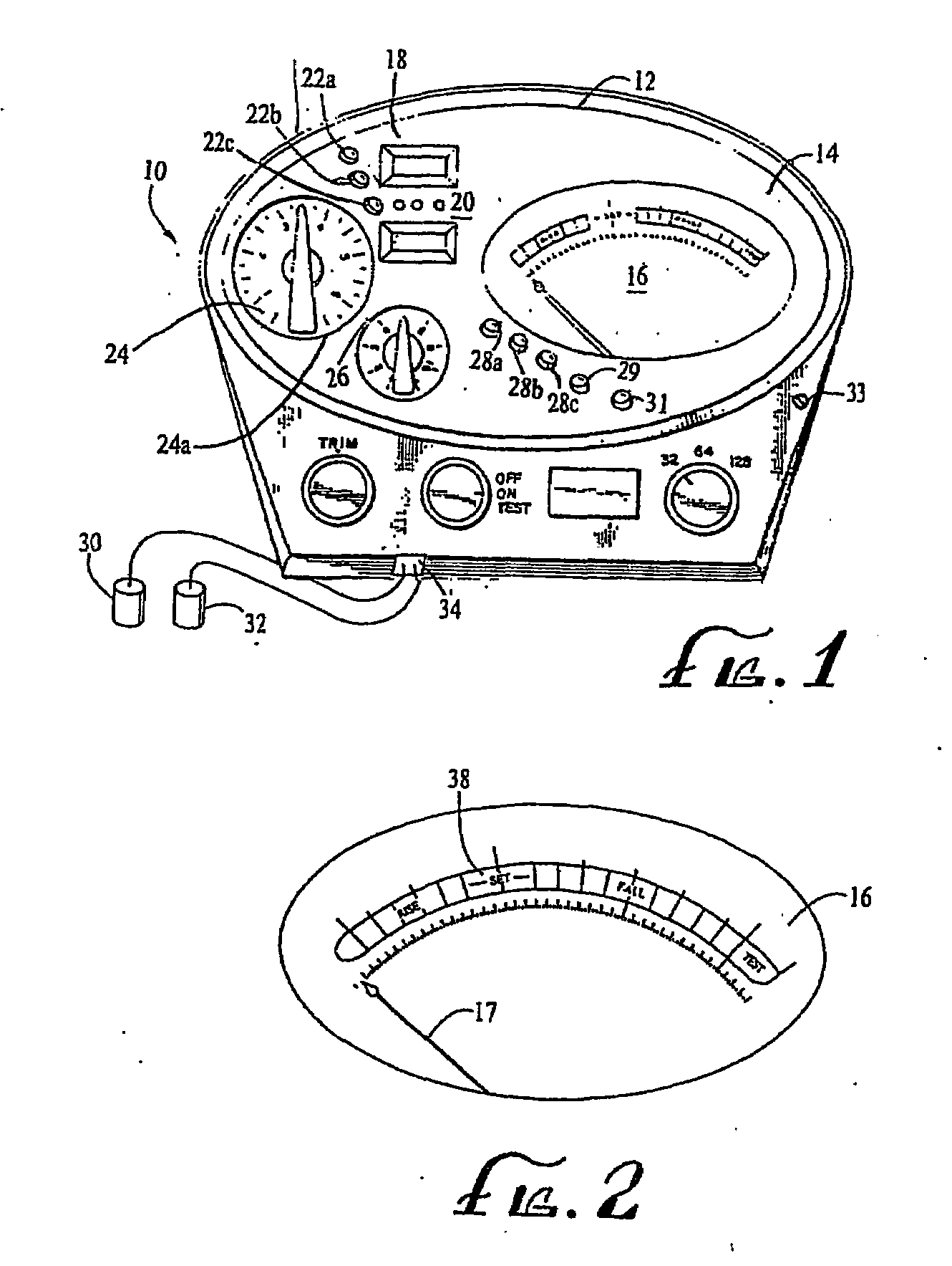
[0017]FIG. 1 is a front view in perspective of a preferred embodiment of a device that has been constructed in accordance with the invention for measuring and indicating changes in resistance of a living body. The device 10 comprises a housing 12 having a window 14 through which a meter 16 is visible. As will be explained below, the meter is utilized to display values of, and changes in, the body resistance of a person being audited by the device (hereinafter, simply “body resistance”). Those skilled in the art will recognize that displays other than the type of meter described herein are within scope of the invention.

[0018]The case 12 includes a second window 18 for viewing a display 20. The display 20 is preferably a liquid crystal display (LCD) that selectively displays such information as the date, the time, tone arm position, tone arm movement, elapsed time during the auditing session, chosen display language and other pertinent information.

[0019]Three buttons 22A-C are associa...


PUM


Abstract

An improved device for indicating and measuring small variations in the resistance of a living body is disclosed which utilizes a central processing unit to digitally process sensed body resistances and drive a resistance-indicating display while compensating for the effects of component aging, component tolerances and component temperatures. The device includes an automatic calibration circuit that is automatically activated on each powering up of the device to measure and store measurement values for a plurality of synthesized body resistances that are used to form a compensation model against which sensed body resistances are, subsequently compared for automatic adjustment of display driving measurement values. The central processing unit additionally adjusts the gain of the meter-driving signal by a gain factor dependant on a user-selected meter-sensitivity setting to avoid previously experienced difficulties in monitoring small changes in body resistance caused by difficulty in setting the initially desired meter reading at certain meter-range values, as well as occasional false and unexpected reversals of meter reading as the meter's range was adjusted.

Description

[0001]This application claims the priority of U.S. Provisional Application No. 60 / 455,948 filed Mar. 19, 2003.[0002]This invention relates to an improved device for indicating and measuring variations in the resistance of a living body.BACKGROUND[0003]Devices for measuring and displaying small changes in the resistance of a living body have previously been disclosed in U.S. Pat. No. 3,290,589 and U.S. Pat. No. 4,459,995 as well as U.S. Pat. No. 6,011,992. These devices generally include a resistance measuring circuit, an amplifier circuit and an indicator circuit. In operation, the device measures the small resistance changes utilizing the resistance measuring circuit to generate a measurement signal indicative of the magnitude of resistance. The measurement signal is then amplified by the amplifier circuit, and the amplified signal is used to drive a display such as an electromagnetically-responsive needle of a meter. The reliability of the readings has depended not only proper cal...

Claims


Application Information

Patent Timeline
Patent Type & Authority Applications(United States)
IPC IPC(8): A61B5/05A61B5/053
CPCA61B5/053
Inventor HUBBARD, LAFAYETTE RONSTARKEY, NORMAN F.STINNETT, RICHARDLILLIHAUGEN, TRENTTEMPLES, JOHN
Owner CHURCH OF SPIRITUAL TECH
Why Eureka
Try Eureka