Implant release mechanism

Active Publication Date: 2008-06-12
COOK MEDICAL TECH LLC
14 Cites 136 Cited by

AI-Extracted Technical Summary

Problems solved by technology

With some prior art stent delivery systems, as soon as the covering sheath is withdrawn to expose the underlying stent, the distal end of the stent expands in a rapid and irregular way, with the risk that one or more of the struts of the stent is deformed irregularly, such as being bent backwards.
The risk of such an occurrence is increased in cases where the distal end of the delivery device on which the stent is located is not in the middle of the vessel.
Moreover, in the final stages of deployment, when the sheath slides over and beyond the distal end of the stent, this will expand in a manner which is difficult to control.
This lack of control makes the placement of the implant less accurate and can also lead to damage to the intima of the vessel.
These problems tend to be exacerbated in the deployment of dissection stents f...

Method used

[0036]The connection device 26 is designed to accept a syringe to facilitate the introduction of reagents into the inner catheter 24. The guide wire catheter 24 is in fluid communication with apertures 28 in the flexible tip 20. Therefore, reagents introduced into connection device 26 will flow to and emanate from the apertures 28.
[0069]Thus, in contrast to the prior art example of FIGS. 1 and 2, it is only necessary to have a single wire actuation section 50 to actuate the restraining wires 62 to...

Benefits of technology

[0014]The provision of at least one restraining wire which can restrain both ends of an implant can reduce the number of restraining devices required to hold the implant in its compressed state prior to its deployment, thereby reducing the volume of the components of the delivery device and therefore enabling a reduction in its outer diameter. This allows for the provision of smaller delivery devices which can be used to deliver implants in smaller lumens.
[0015]Furthermore, the or each common release wire can be manipulated by a single release mechanism, simplifying the proximal end of the deployment device w...

Abstract

An implant release mechanism for releasing, for example, a stent ( 60 ) is provided with three restraining wires ( 62 ) which pass in the space between a wire guide catheter ( 24 ) and a pusher sheath or dilator ( 30 ) and are arranged substantially equi-angularly threrearound. Each restraining wire ( 62 ) holds both the proximal and distal ends of the stent ( 60 ), in this case each holding a proportion of the ends of the stent ( 60 ). When the restraining wires ( 62 ) are pulled they will first unwrap from the proximal end of the stent ( 60 ) and will then release the distal end of the stent ( 60 ) so as to allow the stent to become fully deployed within the lumen of the patient. The use of common release wires improves deployment of implants and reduces the number and volume of components in the device, thereby allowing it to occupy a smaller volume.

Application Domain

Technology Topic

DilatorStent +1

Image

  • Implant release mechanism
  • Implant release mechanism
  • Implant release mechanism

Examples

  • Experimental program(1)

Example

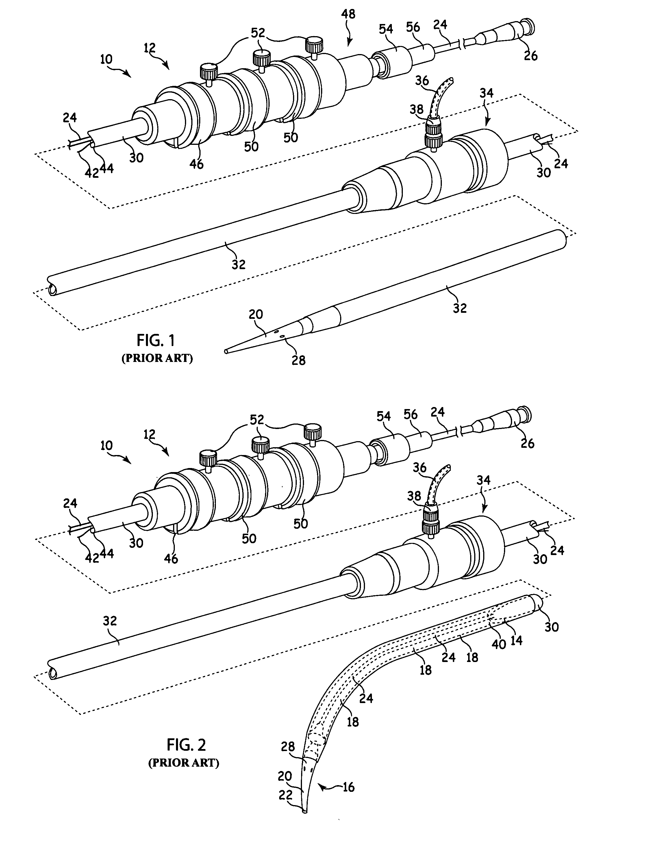
[0032]Referring to FIGS. 1 and 2, there is shown an example of known delivery device, which is useful in understanding the principles of the release mechanism taught herein. The delivery device 10, hereinafter referred to as the introducer, includes an external manipulation section 12 which is operated by a surgeon or clinician and a distal end which is introduced intraluminally into a patient. The distal end includes a distal attachment region 14 and a proximal attachment region 16. The distal attachment region 14 and the proximal attachment region 16 secure the distal and proximal ends of the implant 18, respectively.
[0033]During the medical procedure to deploy the implant 18, the distal end of the device 10 will travel through the patient's lumen to a desired deployment site. The external manipulation section 12, which is acted upon by a surgeon to manipulate the introducer, remains outside of the patient throughout the procedure.
[0034]The proximal attachment region 16 of the introducer 10 includes a flexible dilator tip 20, which is typically provided with a bore 22 therein for receiving a guide wire (not shown) of conventional type. The longitudinal bore 22 also provides a channel for the introduction of medical reagents. For example, it may be desirable to supply a contrast agent to allow angiography to be performed during the placement and deployment phases of the medical procedure.
[0035]A guide wire catheter 24, conventionally made from a flexible thin walled metal tube, is fastened to the flexible tip 20. The guide wire catheter 24 is flexible so that the introducer 10 can be advanced along a relatively tortuous vessel, starting from, for example, the femoral artery, and so that the distal attachment region 14 can be longitudinally and rotationally manipulated. The guide wire catheter 24 extends through the introducer 10 to the manipulation section 12, terminating at a connection device 26, in conventional manner.
[0036]The connection device 26 is designed to accept a syringe to facilitate the introduction of reagents into the inner catheter 24. The guide wire catheter 24 is in fluid communication with apertures 28 in the flexible tip 20. Therefore, reagents introduced into connection device 26 will flow to and emanate from the apertures 28.
[0037]A pusher sheath or rod 30 (hereinafter referred to as a pusher member), typically made from a plastics material, is mounted coaxially over and radially outside of the guide wire catheter 24. The pusher member 30 is “thick walled”, that is the thickness of its wall is preferably several times greater than that of the guide wire catheter 24.
[0038]A sheath 32 extends coaxially over and radially outside of the pusher member 30. The pusher member 30 and the sheath 32 extend distally to the manipulation region 12.
[0039]The implant 18, which may be a stent, a stent-graft, vena cava filter, occlusion device or any other implant or prosthesis deliverable by such a device 10, is retained in a compressed condition by the sheath 32. The sheath 32 extends distally to a sheath manipulator and haemostatic sealing unit 34 of the external manipulation section 12. The haemostatic sealing unit 34 includes a haemostatic seal (not shown) and a side tube 36 held to the unit 34 by a conventional luer lock 38.
[0040]The sheath manipulator and haemostatic sealing unit 34 also includes a clamping collar (not shown) that clamps the sheath 32 to the haemostatic seal and a silicone seal ring (not shown) that forms a haemostatic seal around the pusher rod 30. The side tube 38 facilitates the introduction of medical fluids between the pusher rod 30 and the sheath 32. Saline solution is typically used.
[0041]During assembly of the introducer 10, the sheath 32 is advanced over the proximal end of the flexible tip 20 of the proximal attachment region 16 while the implant 18 is held in a compressed state by an external force. A suitable distal attachment (retention) section (not visible in this view) is coupled to the pusher rod 30 and retains a distal end 40 of the implant 18 during the procedure. The distal end of the implant 18 is provided with a loop (not shown) through which a distal trigger wire 42 extends. The distal trigger wire also extends through an aperture (not shown in FIGS. 1 and 2) in the distal attachment section 40 into an annular region 44 between the inner catheter 24 and the pusher rod 30. The distal trigger wire 42 extends through the annular space 44 to the manipulation region 12 and exits the annular space 44 at a distal wire release mechanism 46.
[0042]A proximal portion of the external manipulation section 12 includes at least two trigger wire actuation sections 46, 50 mounted on a body 48, in turn mounted onto the pusher member 30. In this example there are provided three wire release mechanisms. The guidewire catheter 24 passes through the body 48. The distal wire release mechanism 46 and the proximal wire release mechanism 50 are mounted for slidable movement on the body 48.
[0043]The positioning of the proximal and distal wire release mechanisms 46 and 50 is such that the proximal wire release mechanism 46 must be moved before the distal wire release mechanism or mechanisms 50 can be moved. Therefore, the distal end of the implant 18 cannot be released until a self-expanding zigzag stent thereof has been released. Clamping screws 52 prevent inadvertent early release of the prosthesis 18.
[0044]A haemostatic seal (not shown) is included so that the release wires can extend out through the body 48 without unnecessary blood loss during the medical procedure.
[0045]A proximal portion of the external manipulation section 12 includes a pin vice 54 mounted onto the proximal end of the body 48. The pin vice 54 has a screw cap 56. When screwed in, vice jaws (not shown) of the pin vice 54 clamp against or engage the guidewire catheter 24. When the vice jaws are engaged, the guidewire catheter 24 can only move with the body 48 and hence it can only move with the pusher member 30. With the screw cap 56 tightened, the entire assembly can be moved together as one piece.
[0046]Once the introducer assembly 12 is in the desired deployment position, the sheath 32 is withdrawn to just proximal of the distal attachment section 14. This action releases the middle portion of the implant 18, in this example a stent or stent-graft, so that it can expand radially. Consequently, the stent or stent-graft 18 can still be rotated or lengthened or shortened for positioning. The proximal end of the self-expanding stent, however, is still retained at the flexible tip 16 by means of the release wires. Also, the distal end of the stent or stent-graft 18 will still retained within the sheath 32.
[0047]Next, the pin vice 54 is released to allow small movements of the guidewire catheter 24 with respect to the pusher rod 30 to allow the stent or stent-graft 18 to be lengthened, shortened, rotated or compressed for placement within the lumen. X-ray opaque markers (not shown) may be placed along the stent or stent-graft 18 to assist with placement of the prosthesis.
[0048]When the proximal end of the stent or stent-graft 18 is in place, the proximal trigger wire is withdrawn by distal movement of the proximal wire release mechanism. The proximal wire release mechanism 50 and the proximal trigger wire can be completely removed by passing the proximal wire release mechanism 50 over the pin vice 54, the screw cap 56 and the connection unit 26.
[0049]Next, the screw cap 56 of the pin vice 54 is loosened, after which the inner catheter 24 can be pushed in a proximal direction to move the flexible tip 20 in a proximal direction. When the flexible tip 20 no longer surrounds the end of the stent or stent-graft 18, it expands to engage the lumen walls of the patient. From this stage on, the proximal end of the stent or stent-graft 18 cannot be moved again.
[0050]Once the proximal end of the stent or stent-graft 18 is anchored, the sheath 32 is withdrawn distally of the distal attachment section 14, which withdrawal allows the distal end of the stent or stent-graft 18 to expand. At this point, the distal end of the stent or stent-graft 18 may still be repositioned as needed.
[0051]The example prior art device shown in FIGS. 1 and 2, as would be readily apparent to the person skilled in the art, includes separate release wire mechanisms for releasing the proximal and distal ends of the implant 18, as well as specific locks and release mechanisms 50, 52 for operating the release wires.
[0052]Referring now to FIG. 3, there is shown an embodiment of implant release mechanism, in this case being part of a delivery device analogous to that of FIGS. 1 and 2 but incorporating an example of the release mechanism taught herein.
[0053]The embodiment of FIG. 3 is shown holding a stent 60, in this example a dissection stent, although it is to be understood that the principles taught herein can be used to hold and restrain any implant, including other forms of stent, stent-grafts, vena cava filters, occlusion devices and any other implants and prostheses which can be delivered by such delivery devices.
[0054]The example in FIG. 3 shows a single restraining wire 62 which passes in the space between the wire guide catheter 24 and the pusher sheath or dilator 30. At an end of the dilator 30 which provides the distal fixation point 64, there are provided two bores 66, 68 which, in this example, are at an angle of around 90° to one another so as to enable the restraining wire 62 to pass through both bores to provide a loop 70 as shown in FIG. 3 in particular.
[0055]At the proximal end of the implant attachment region and in particular within the wall of the flexible tip 20 adjacent the proximal end of the implant 60, there are provided bores 72, 74 equivalent to the bores 66, 68 in the distal attachment region, these being adjacent a proximal fixation position 62. The restraining wire 62 also forms a loop 76 as it passes through the two bores 72, 74.
[0056]The end of the restraining wire 62 is fixed, for example by an interference fit or by suitable adhesive, to a location on the inside of the flexible tip 20 but in such a manner that the wire 62 can be withdrawn from its fixation location upon application of a pulling force by the surgeon through an appropriate control element or handle at the external manipulation section 12 of the delivery device 10. The manner in which the end of the restraining wire 62 is held within the flexible tip 20 is conventional in the art so need not be described in further detail herein.
[0057]FIG. 3 shows a single restraining wire 62. However, in the preferred embodiment, a plurality of restraining wires 62 is provided, most preferably three, arranged substantially equi-angularly around the pusher sheath 30 and dilator 20. It is considered that using three restraining wires 62 provides the optimum solution in terms of restraining the implant in a substantially compressed condition on the delivery device until it has to be deployed, whilst not providing too many components within this tip section of the delivery device, thereby enabling the delivery device to have a small outer diameter.
[0058]In the view of FIG. 3, the sheath 32 which would normally cover the implant 60 and part of the flexible tip 20 adjacent the implant 60 has been removed, such that the implant 60 is no longer kept in its compressed state by the force applied to it normally by the sheath 32. As can be seen in FIG. 3, in this condition, the central portion of the stent 60 has expanded to the extent possible whilst its proximal and distal ends remain constrained at the fixation points 62 and 64.
[0059]The ends of the stent 60 will only be released to expand once the restraining wires 62 have been removed, typically by applying a pulling force to the wires 62 from the external manipulation section 10, in a manner known in the art. In this particular case, since there is a common restraining wire 62 holding both the proximal and distal ends of the stent 60 (particularly three restraining wires 62 each holding a proportion of the ends of the stent 60) when the restraining wire or wires 62 are pulled they will first unwrap themselves from the proximal end of the stent 60. This will typically happen as the ends of the release wires 62 pass through their respective bores 74 then into the bores 72. Thus, the proximal end of the stent 60 is released to expand first.
[0060]Upon further pulling of the same restraining wire or wires 62, preferably using the same release mechanism, the end of the restraining wire will eventually feed through the bores 68 and then the bores 66, thereby to release the distal end of the stent 60 so as to become fully deployed within the lumen of the patient.
[0061]Referring now to FIG. 4, there is shown the embodiment of implant release mechanism of FIG. 3; in the course of the assembly of a stent 60 onto the delivery device 10. FIG. 4 is shown in schematic form simply to illustrate the provision of three restraining wires 62, as the method of fixing the ends of the stent 60 is described in further detail in connection with FIGS. 5 to 8. In FIG. 4, the stent 60 is shown in a fully expanded form, before its ends are constrained to the proximal and distal fixation points 70, 76 of the delivery device. The restraining wires 62 are also shown in loose form, prior to fitting, as described above and also below.
[0062]A holding cap 80 is provided, if desired, to hold the end of the flexible tip 20 during the assembly process.
[0063]Referring now to FIG. 5, there is shown an embodiment of threading scheme for coupling the restraining wires 62 to the distal end of the stent 60. In this embodiment, there is provided a common thread 82, which may be a conventional suture thread, tied at each apex 84 of the endmost stent ring of the stent 60. For this purpose, the suture thread 82 is knotted at each apex 84 and is preferably of such a length that it allows this end of the stent 60 to expand as much as the other sections of the stent 60 or by any amount considered appropriate for the particular medical application in question.
[0064]Each restraining wire 62 is looped around the portion of suture thread 82 between each apex 84, with the two ends 86, 88 being fed into the appropriate bores 66, 68, respectively. Thus, when the restraining wires 62 are pulled into their restraining position, as shown in FIG. 3 and in particular in FIG. 6, the restraining wires 62 pull the suture thread 82 into the loop 70 formed by the restraining wire 62 between the two bores 66, 68, thereby pulling the distal end of the stent 60 into the compressed form shown in FIG. 6.
[0065]The proximal end of the stent 60 is also restrained by the restraining wires 62, in a manner similar to that shown in FIGS. 5 and 6. This is shown in FIGS. 7 and 8, in which common reference numerals have been used and in which in the apices of the proximal-most stent ring identified by reference numeral 84′ and the suture thread is identified by reference numeral 82′.
[0066]A common restraining wire 62 will restrain, in the example shown in FIGS. 3 to 8, a proportion of the distal end of stent 60 as well a proportion of the proximal end of the stent 60. In the example of FIGS. 3 to 8, each restraining wire 62 will restrain a third of the distal end of the stent 60 as well as a third of the proximal end of a stent 60.
[0067]Upon withdrawing of the restraining wire 62, therefore, this will be released from its holding position within the flexible tip 20 and will first unravel from the proximal end of the stent 60. Eventually, as it is withdrawn further, each restraining wire 62 will unravel from the distal end of the stent 60. In the preferred embodiment, the three restraining wires 62 are actuated by the same actuating mechanism, for example a handle, possibly of the type shown in FIGS. 1 and 2, such that the entirety of the proximal end of the stent 60 will be released at the same time. Subsequently, the entirety of the distal end will be released.
[0068]In some applications it may be desired to release the proximal and/or distal ends of the stent 60 in sections, in which case the individual restraining wires 62 could be withdrawn separately from one another.
[0069]Thus, in contrast to the prior art example of FIGS. 1 and 2, it is only necessary to have a single wire actuation section 50 to actuate the restraining wires 62 to release the stent 60. This has the advantage of providing only a single actuation device for a surgeon to operate, thereby simplifying the surgeon's task. Furthermore, since a single release mechanism can be used, the release of the entirety of the stent 60 can be effected by the same procedure, (for example the same withdrawing or pulling action by the surgeon) which therefore enables this deployment phase of the stent 60 to be carried out smoothly and more accurately than with prior art devices.
[0070]The restraining wires 62 can be made of any suitable material, including Nitinol any other flexible metal or alloy, a polymeric fibre or any other suitable material.
[0071]The embodiment of FIGS. 3 to 8 includes three restraining wires 62. However, the teachings herein are not limited to this number. It is envisaged that in some applications a single release wire 62 can be provided to restrain the entirety of each end of the stent 60 or other device to be implanted. Similarly, there may be provided two restraining wires or more than three. Provision of three is, however, preferred in that it optimises the tensile force required to withdraw the restraining wires 62 in conjunction with the overall volume required for the assembly.
[0072]The embodiment of FIGS. 3 to 8 also uses a suture thread 82, 82′ around which the restraining wires are looped. However, this particular arrangement of suture thread 82, 82′ is not essential. It is envisaged, for example, that in some applications the restraining wire 62 can be looped around the apices of the stent sections, without any need for a holding thread of the type shown in FIGS. 3 to 8. In another embodiment, each apex 84 could be provided with its own individual loop of suture thread, through which a restraining wire 62 can be made to pass. In yet another embodiment, some of the apices 84 could be provided with a long loop of suture thread which is then passed through adjacent apices 84 which are not provided with such suture thread and through which the restraining wire 62 can be made to pass, in a manner similar to that described in US-2006/0142836.
[0073]Although the embodiments disclosed above have been described in connection with a stent, this restraining mechanism can be used to restrain any implant which can be carried by such a delivery device. It can be used, for example, to hold any other type of stent, a stent-graft, a filter such as that disclosed, for example, in US-2003/0199918, an occlusion device or any other implant or prosthesis deliverable by such a delivery device.
[0074]Although specific embodiments have been described above they are not to be considered limiting to the invention. The scope of the teachings herein is as set out in the appended claims.

PUM

no PUM

Description & Claims & Application Information

We can also present the details of the Description, Claims and Application information to help users get a comprehensive understanding of the technical details of the patent, such as background art, summary of invention, brief description of drawings, description of embodiments, and other original content. On the other hand, users can also determine the specific scope of protection of the technology through the list of claims; as well as understand the changes in the life cycle of the technology with the presentation of the patent timeline. Login to view more.

Similar technology patents

Classification and recommendation of technical efficacy words

  • Reduce volume
  • Reduce outer diameter

Flash storage chip and flash array storage system

ActiveUS20080052451A1Reduce volumeImprove data transmission rateMemory adressing/allocation/relocationData transmissionPCI Express
Owner:PHISON ELECTRONICS

Devices and methods for placement of partitions within a hollow body organ

InactiveUS20070167960A1Reduce volumeSuture equipmentsStapling toolsTissue acquisitionBody organs
Owner:ETHICON ENDO SURGERY INC

Optical cable

ActiveUS20070104429A1Reduce outer diameterIncrease in transmission lossFibre mechanical structuresTension memberMode field diameter
Owner:SUMITOMO ELECTRIC IND LTD +1

Semiconductor device and semiconductor device manufacturing method

InactiveUS20090008744A1Reduce outer diameterContact resistanceTransistorSolid-state devicesEngineeringSemiconductor
Owner:PS4 LUXCO SARL

Planetary gear reduction mechanism

InactiveUS20140031165A1Reduce outer diameterReduce gear ratioToothed gearingsGearing detailsOut of phaseRotational axis
Owner:NITTAN VALVE CO LTD

Glow plug terminal and glow plug

ActiveUS20130180975A1Reduce outer diameterDiameter of outerLine/current collector detailsElectrically conductive connectionsEngineeringFlange
Owner:NGK SPARK PLUG CO LTD
Why Eureka
Try Eureka