Elongated femoral component

a femoral component and flexion gap technology, applied in the field of knee joint prosthesis, can solve the problems of increased flexion gap relative to flexion gap, and increased surgical resection,

Inactive Publication Date: 2008-06-12
BIOMET MFG CORP
View PDF75 Cites 181 Cited by
  • Summary
  • Abstract
  • Description
  • Claims
  • Application Information

AI Technical Summary

Problems solved by technology

The patient may later require a fully constrained knee joint prosthesis because the patient is exhibiting instability.
Moreover, during the surgical procedure, a surgeon may initially wish to implant a cruciate retaining type knee joint prosthesis and subsequently realize that a posterior stabilized or a fully constrained knee joint prosthesis is required, which may lead to additional surgical resections, as well as surgical time and cost.
It has also been suggested in the literature that removal of intercondylar bone may predispose to intercondylar bone fracture.
Additionally, resection of the PCL results in an increase in flexion gap relative to extension gap.
In some patients, the PCL may be absent or incompetent and balancing is, therefore, difficult to achieve.
However, the surgeon may find interoperatively in trial, that the preselected prosthesis may not provide the best function of the knee joint and that surgical adjustments in the knee joint are required.
However, if the increase in flexion gap is greater than the surgeon had interoperatively evaluated it to be, the knee joint may postoperatively become loose in flexion which can affect the stability and balance of the implanted knee joint.
Additionally, the remaining ligaments in the patients knee joint may become lax and this can also affect stability and wear in the prosthetic knee joint.
This is because there may be more edge loading or rotation in the bearing of the prosthetic knee joint and that may be disadvantageous for the knee joint prosthesis patient in the long term.
However, by removing the PCL, the flexion gap will increase and further bone resection may be required.
This can restrict flexion of the knee, which might not be acceptable to an active knee joint prosthesis patient.
Currently, many surgeons are reluctant to use a posterior augment in the knee for fear of future deterioration of the knee joint.
However, this may create problems with patella tracking in the knee joint and the knee joint prosthesis patient may find this to be disadvantageous.
The use of a femoral component having a ML width that does not at least approximately match the ML width of the femur is undesirable as it can restrict flexion of the knee.
Conventional knee joint prostheses do not provide multiple femoral components of varying ML widths to match femurs having varying ML widths, including femurs that have a disproportionally wide medial condyle.

Method used


Image

  • Elongated femoral component
  • Elongated femoral component
  • Elongated femoral component

Examples


Embodiment Construction

[0041]The following description of the embodiment(s) directed to providing an elongated femoral component for the posterior stabilized and the fully constrained knee joint prosthesis are merely exemplary in nature and are not intended to limit its application or uses. The present invention is described in detail below with respect to floating bearing type knee joint prostheses. However, those skilled in the art will appreciate that the present invention is clearly not limited to only knee joint prostheses that employ floating bearings, but may be employed with any other type of knee joint prosthesis, such as a fixed bearing knee joint prosthesis.

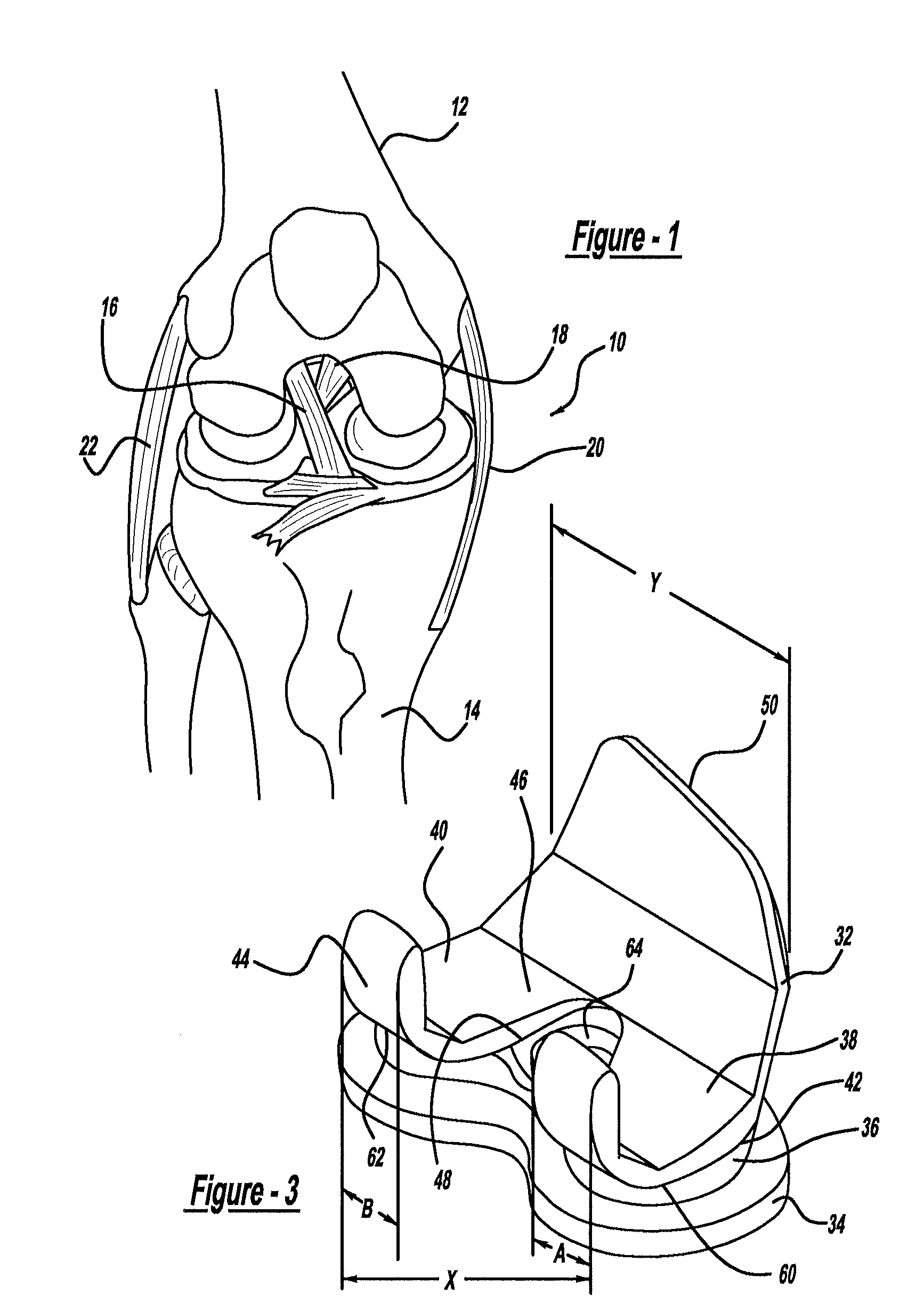
[0042]Referring to FIG. 1, an anatomical knee joint 10 which provides articulating motion between a femur 12 and a tibia 14 is illustrated in detail. The anatomical knee joint 10 includes a posterior cruciate ligament (PCL) 16 and an anterior cruciate ligament (ACL) 18, which cross each other within the knee joint 10. The PCL and ACL ligamen...


PUM


Abstract

A plurality of knee joint prostheses comprise a first femoral implant and a second femoral implant. The first femoral implant has a first maximum interior anterior to posterior dimension, a first maximum overall exterior anterior to posterior dimension, a first lateral condyle, and a first medial condyle. The second femoral implant has a second maximum interior anterior to posterior dimension that is substantially the same as the first maximum interior anterior to posterior dimension, a second maximum overall exterior anterior to posterior dimension that is different than the first maximum overall exterior anterior to posterior dimension, a second lateral condyle having a medial to lateral dimension that is substantially the same as a medial to lateral dimension of the first lateral condyle, and a second medial condyle having a medial to lateral dimension that is different than a medial to lateral dimension of the first medial condyle.

Description

CROSS-REFERENCE TO RELATED APPLICATION[0001]This application is a continuation-in-part of U.S. patent application Ser. No. 10 / 614,550 filed on Jul. 7, 2003, which is a continuation-in-part of U.S. patent application Ser. No. 09 / 855,939, which was filed on May 15, 2001 and issued as U.S. Pat. No. 6,589,283 on Jul. 8, 2003. The disclosure of the above applications are incorporated herein by reference.BACKGROUND OF THE INVENTION[0002]1. Field of the Invention[0003]The present invention relates generally to a knee joint prosthesis, which replaces the articulating knee portion of the femur and tibia, and more particularly, to a knee joint prosthesis system, which includes elongated femoral components for posterior stabilized and fully constrained applications.[0004]2. Discussion of the Related Art[0005]The knee joint is a complex articulating structure. The knee joint includes a femur, which articulates with a tibia, and a patella, which acts as a protective shield for the articulating k...

Claims


Application Information

Patent Timeline
Patent Type & Authority Applications(United States)
IPC IPC(8): A61F2/38A61F2/30
CPCA61F2/3859A61F2002/30616A61F2/3886
Inventor METZGER, ROBERTHERSHBERGER, TROY W.DONALDSON, THOMAS
Owner BIOMET MFG CORP
Why Eureka
Try Eureka