Autonomous surface cleaning robot for wet and dry cleaning

a technology of cleaning robots and cleaning fluids, applied in the direction of floor surfacing/polishing machines, travelling automatic control, cationic surface active compounds, etc., can solve the problems of deteriorating affecting the effectiveness of cleaning fluid, and no teaching of affordable autonomous floor cleaning robots for wet cleaning floors in the home, etc., to achieve low cost and affordable home use

Inactive Publication Date: 2008-06-12
IROBOT CORP
View PDF100 Cites 282 Cited by
  • Summary
  • Abstract
  • Description
  • Claims
  • Application Information

AI Technical Summary

Benefits of technology

[0016]The present invention overcomes the problems cited in the prior by providing, inter alia, low cost autonomous robot capable of wet cleaning floors and affordable for home use. The problems of the prior art are addressed by the present invention which provides an autonomous cleaning robot comprising a chassis and a transport drive system configured to autonomously transport cleaning elements over a cleaning surface. The robot is supported on the cleaning surface by wheels in rolling contact with the cleaning surface and the robot includes controls and drive elements configured to control the robot to generally traverse the cleaning surface in a forward direction defined by a fore-aft axis. The robot is further defined by a transverse axis perpendicular to the fore-aft axis.
[0052]An example robot according to the invention has a cleaning width of about 30 cm, and a mass of about 3-5 kg. Such a robot has about 10 cm to about 6 cm of powered cleaning width per kilogram of fully loaded robot, a less efficient version, but still acceptable, could be 3 cm of powered cleaning width per kilogram of robot mass. This cleaning width permits sufficient work to be done per unit time, and the amount of weight is sufficient to provide enough traction for the cleaning width. Moreover, the robot does not become excessively large or inefficient by limiting the amount of weight. This combination provides the best balance of cleaning time versus maneuverability versus manageability.
[0053]Optionally, the powered wet cleaning head includes a powered circulating scrubber that scrubs the surface to be cleaned along a cleaning width line of the robot with the assistance of dispensed fluid. Further, the powered wet cleaning head may include a powered wet vacuum that picks up the waste fluid. Each of these contributes to the cleaning width, and may contribute either to drag or to motive force. The weight placed on the cleaning width may be limited to reduce or otherwise limit the amount of drag.
[0056]Optionally, the tank forms at least one quarter of the outer profile of the robot, wherein engagement of the coupling engagement of completes a substantially smooth outer profile of the robot. Alternatively, the tank forms at least one quarter of the outer peripheral surface of the robot including a part of the perimeter of the shape of constant width, and wherein engagement of the coupling engagement of substantially completes the perimeter of the shape of constant width. In either case, the robot is permitted to autonomously turn to escape confined spaces and corners by virtue of the outer profile, and space is efficiently maximized by avoiding the use of double and triple walls to house the tank within the robot body.

Problems solved by technology

While each of the above examples provide affordable autonomous floor clearing robots for collecting loose particulates, there is heretofore no teaching of an affordable autonomous floor cleaning robot for applying a cleaning fluid onto the floor to wet clean floors in the home.
The cleaning fluid interacts with contaminants on the surface and may dissolve or otherwise emulsify contaminants into the cleaning fluid.
One problem with the manual floor cleaning methods of the prior art is that after cleaning an area of the floor surface, the waste liquid must be rinsed from the mop or sponge, and this usually done by dipping the mop or sponge back into the container filled with cleaning fluid.
The rinsing step contaminates the cleaning fluid with waste liquid and the cleaning fluid becomes more contaminated each time the mop or sponge is rinsed.
As a result, the effectiveness of the cleaning fluid deteriorates as more of the floor surface area is cleaned.
While the traditional manual method is effective for floor cleaning, it is labor intensive and time consuming.
Moreover, its cleaning effectiveness decreases as the cleaning fluid becomes contaminated.
One reason such devices are operator attended is because they weight hundreds of pounds and can cause significant damage in the event of a sensor failure or unanticipated control variable.
A more significant reason is because devices as proposed by Betker et al. are not physically configured to escape or navigate among confined areas or obstacles, nor are they capable of being programmed to escape or navigate among confined areas or obstacles.
The Betker et al. device is in some ways semi-autonomous, but despite its rich sensor complement, it does not address fundamental principles of autonomous operation, including physical configuration and flexible response to its environment.
The Betker et al. device would likely clean for no more than a few minutes before getting stuck and requiring operator intervention.
While the device disclosed by Betker et al. is usable to autonomously wet clean large floor areas, it is not suitable for the home market, and further, lacks many features, capabilities, and functionality of the present invention as described further herein.
In particular, the industrial autonomous cleaning device disclosed by Betker et al. is too large, costly and complex for use in the home and consumes too much electrical power to provide a practical solution for the home wet floor cleaning market.
Another is that its cleaning techniques may not be effective in a robot that could be carried or manually moved by a person, e.g., less than 20 kg.
While Wright et al. describes a self contained wet cleaning device as well as an improved wet cleaning method that separates waste liquid from cleaning fluid, the device is manually operated and appears to lack robotic functionality (motor drive, autonomous control, etc.) and other benefits and features identified in the present disclosure.

Method used


Image

  • Autonomous surface cleaning robot for wet and dry cleaning
  • Autonomous surface cleaning robot for wet and dry cleaning
  • Autonomous surface cleaning robot for wet and dry cleaning

Examples


Embodiment Construction

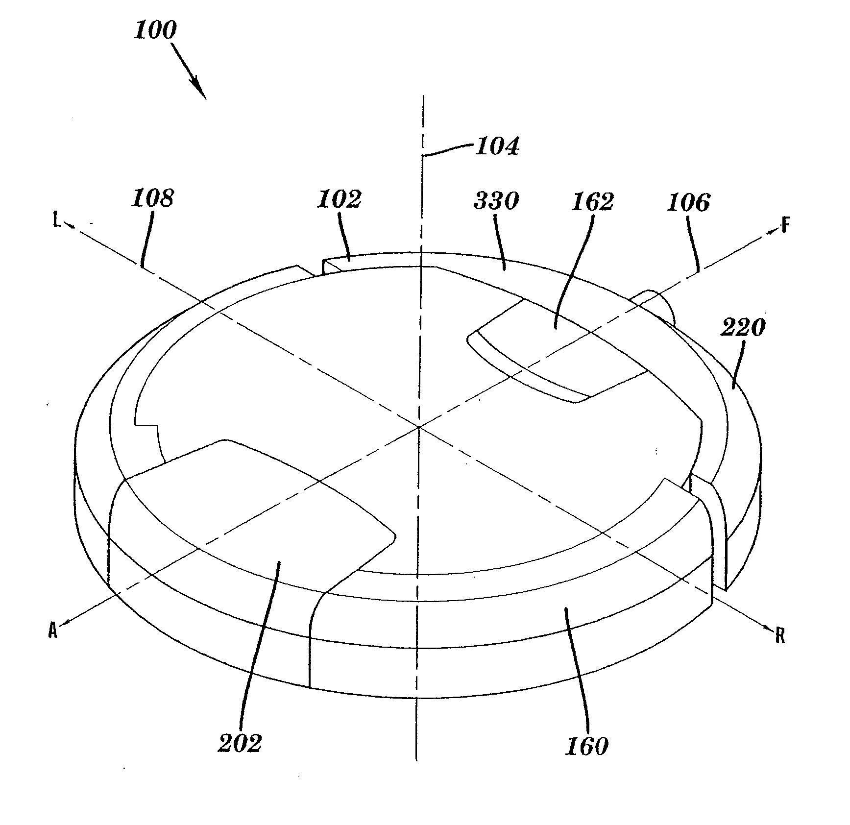
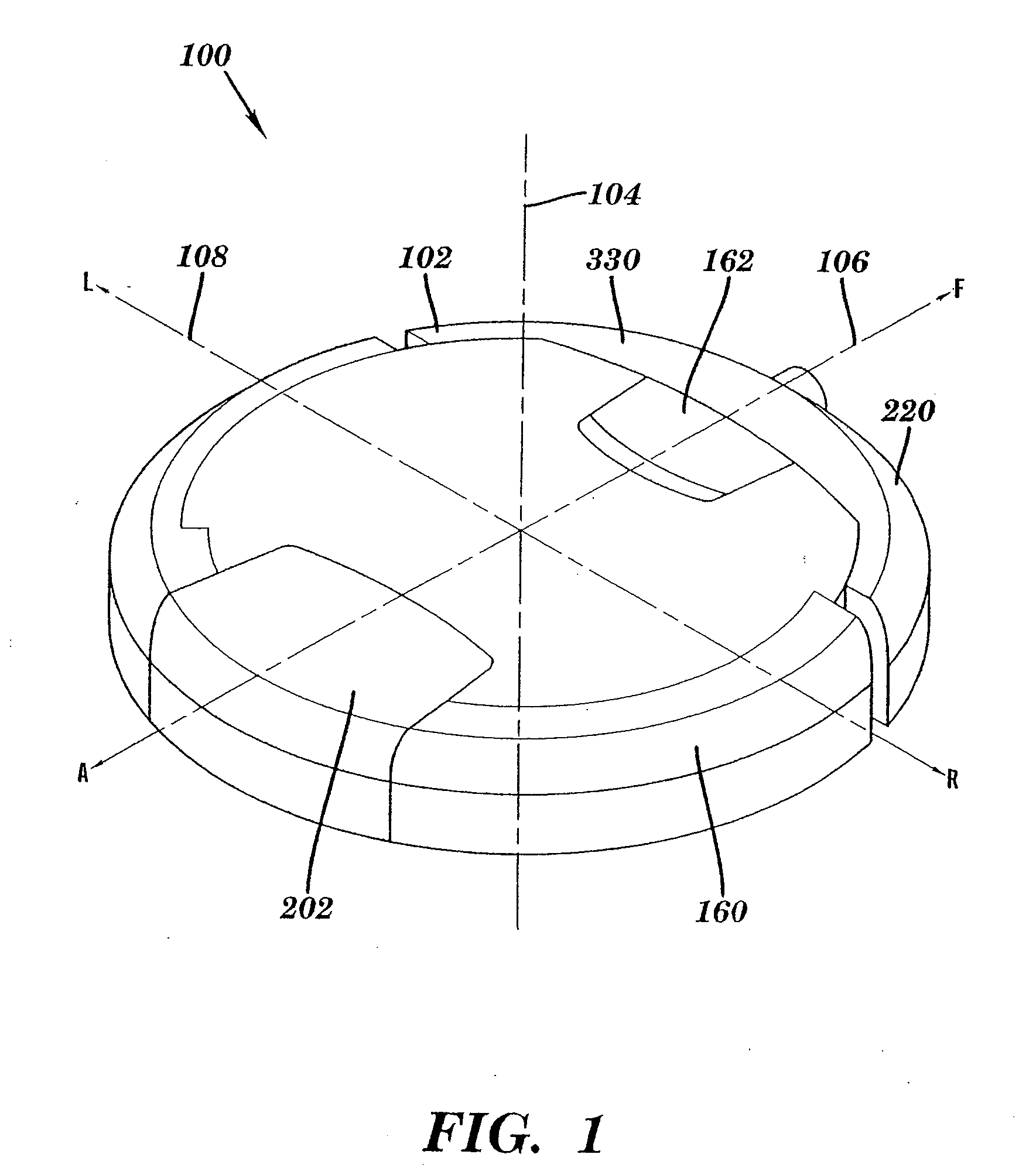
[0122]Referring now to the drawings where like reference numerals identify corresponding or similar elements throughout the several views, FIG. 1 depicts an isometric view showing the external surfaces of an autonomous cleaning robot 100 according to a preferred embodiment of the present invention. The robot 100 is configured with a cylindrical volume having a generally circular cross-section 102 with a top surface and a bottom surface that is substantially parallel and opposed to the top surface. The circular cross-section 102 is defined by three mutually perpendicular axes; a central vertical axis 104, a fore-aft axis 106, and a transverse axis 108. The robot 100 is movably supported with respect to a surface to be cleaned, hereinafter, the cleaning surface. The cleaning surface is substantially horizontal.

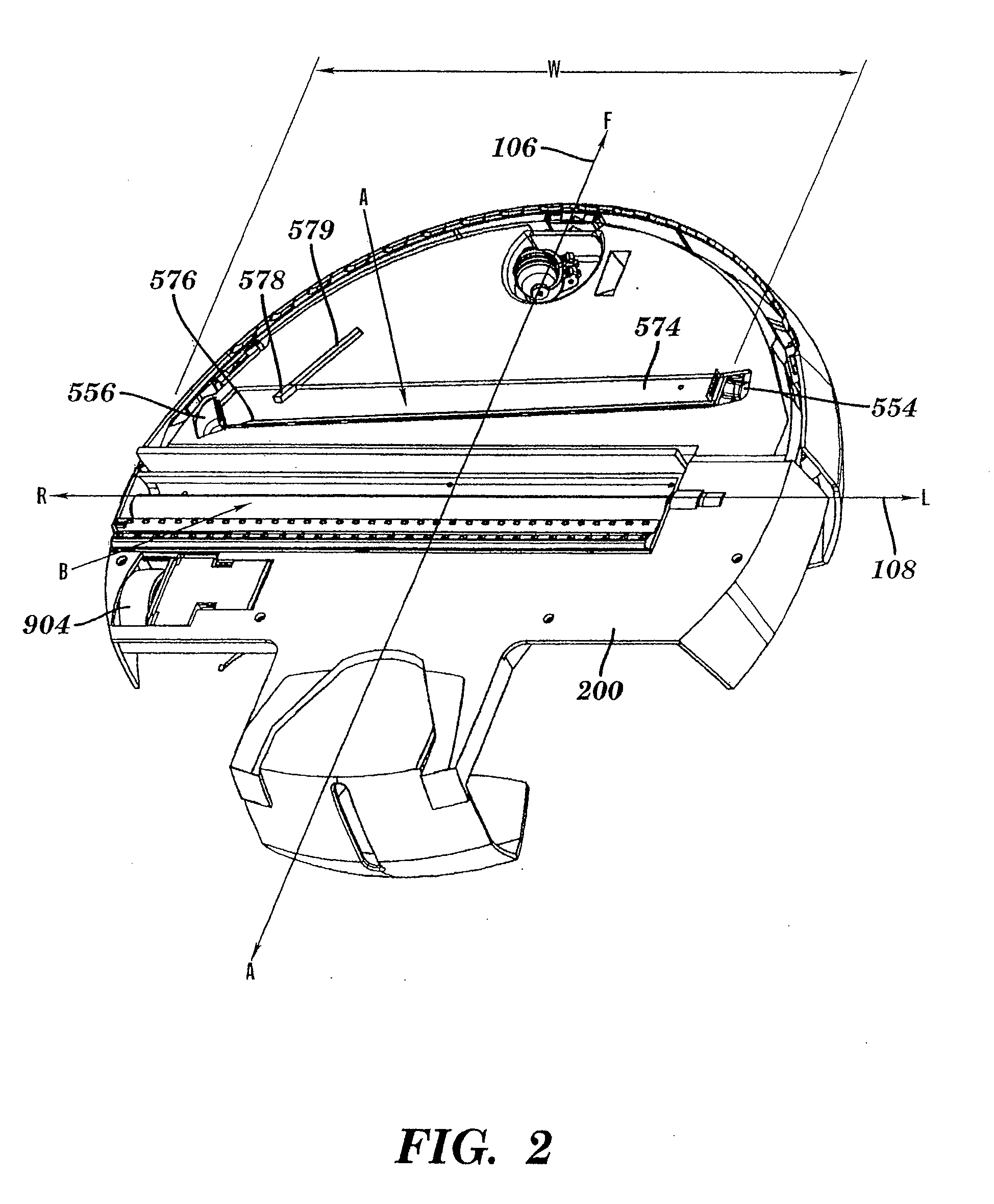
[0123]The robot 100 is generally supported in rolling contact with the cleaning surface by a plurality of wheels or other rolling elements attached to a chassis 200. In a prefer...


PUM


Abstract

An autonomous floor cleaning robot includes a transport drive and control system arranged for autonomous movement of the robot over a floor for performing cleaning operations. The robot chassis carries a first cleaning zone comprising cleaning elements arranged to suction loose particulates up from the cleaning surface and a second cleaning zone comprising cleaning elements arraigned to apply a cleaning fluid onto the surface and to thereafter collect the cleaning fluid up from the surface after it has been used to clean the surface. The robot chassis carries a supply of cleaning fluid and a waste container for storing waste materials collected up from the cleaning surface.

Description

CROSS-REFERENCE TO RELATED APPLICATIONS[0001]This application claims priority under 35 U.S.C. § 119(e) to U.S. Provisional Application Ser. No. 60 / 654,838, the entire disclosure of which is herein incorporated by reference it its entirety. This application also claims priority under 35 U.S.C. § 120 to U.S. application Ser. No. 11 / 134,212, U.S. application Ser. No. 11 / 134,213, U.S. application Ser. No. 11 / 133,796, U.S. application Ser. No. 11 / 207,574, U.S. application Ser. No. 11 / 207,575, and U.S. application Ser. No. 11 / 207,620, the entire disclosures of which are herein incorporated by reference in their entireties.BACKGROUND OF THE INVENTION[0002]The present invention relates to cleaning devices, and more particularly, to an autonomous surface cleaning robot.DESCRIPTION OF RELATED ART[0003]Autonomous robot floor cleaning devices having a low enough end user price to penetrate the home floor cleaning market are known in the art. For example, and U.S. Pat. No. 6,883,201 by Jones et ...

Claims


Application Information

Patent Timeline
Patent Type & Authority Applications(United States)
IPC IPC(8): A47L11/40G06F19/00A47L9/00A47L7/02A47L5/00G05D1/02A47L11/20
CPCA47L5/14A47L7/0028A47L7/0038A47L7/0042A47L9/009A47L11/40A47L11/4016A47L11/4083A47L2201/00B60B33/001B60B33/0021B60B33/0028B60B33/0039B60B33/0049B60B33/0057B60B33/0068B60B33/0073C11D1/62C11D1/75F04D29/4233G05D1/0219G05D1/0225G05D1/0227G05D1/0272G05D2201/0203A47L2201/04Y10S901/01Y10S901/40A47L11/302A47L11/00A47L11/02B60B33/028A47L9/28A47L11/4011A47L11/4041A47L11/4044A47L11/4061A47L11/4066A47L11/4069A47L11/4088A47L2201/022A47L9/10A47L9/2826A47L9/2852A47L9/2857A47L9/2873A47L9/2884A47L11/4005A47L11/4027B60R19/483
Inventor ZIEGLER, ANDREWGILBERT, DUANEMORSE, CHRISTOPHER JOHNPRATT, SCOTTSANDIN, PAULDUSSAULT, NANCYJONES, ANDREW
Owner IROBOT CORP
Why Eureka
Try Eureka