

Entrained flow reactor for gasifying solid and liquid energy sources
a gasification reactor and gasification technology, applied in the direction of gasifier mechanical details, combustible gas purification/modification, combustible gas production, etc., can solve the problems of large thermodynamic stress, crack formation, rapid destruction,
- Summary
- Abstract
- Description
- Claims
- Application Information
AI Technical Summary
Benefits of technology
Problems solved by technology
Method used
Image

Examples
example 1
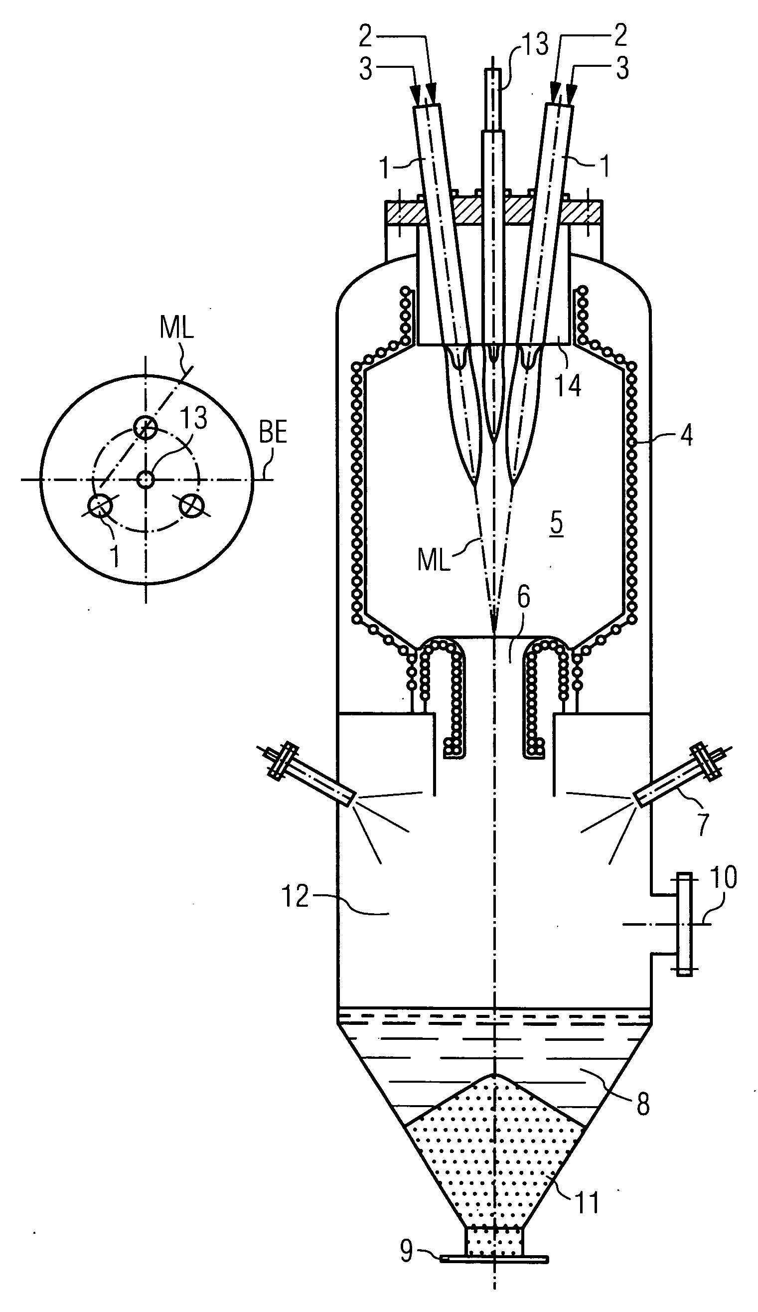
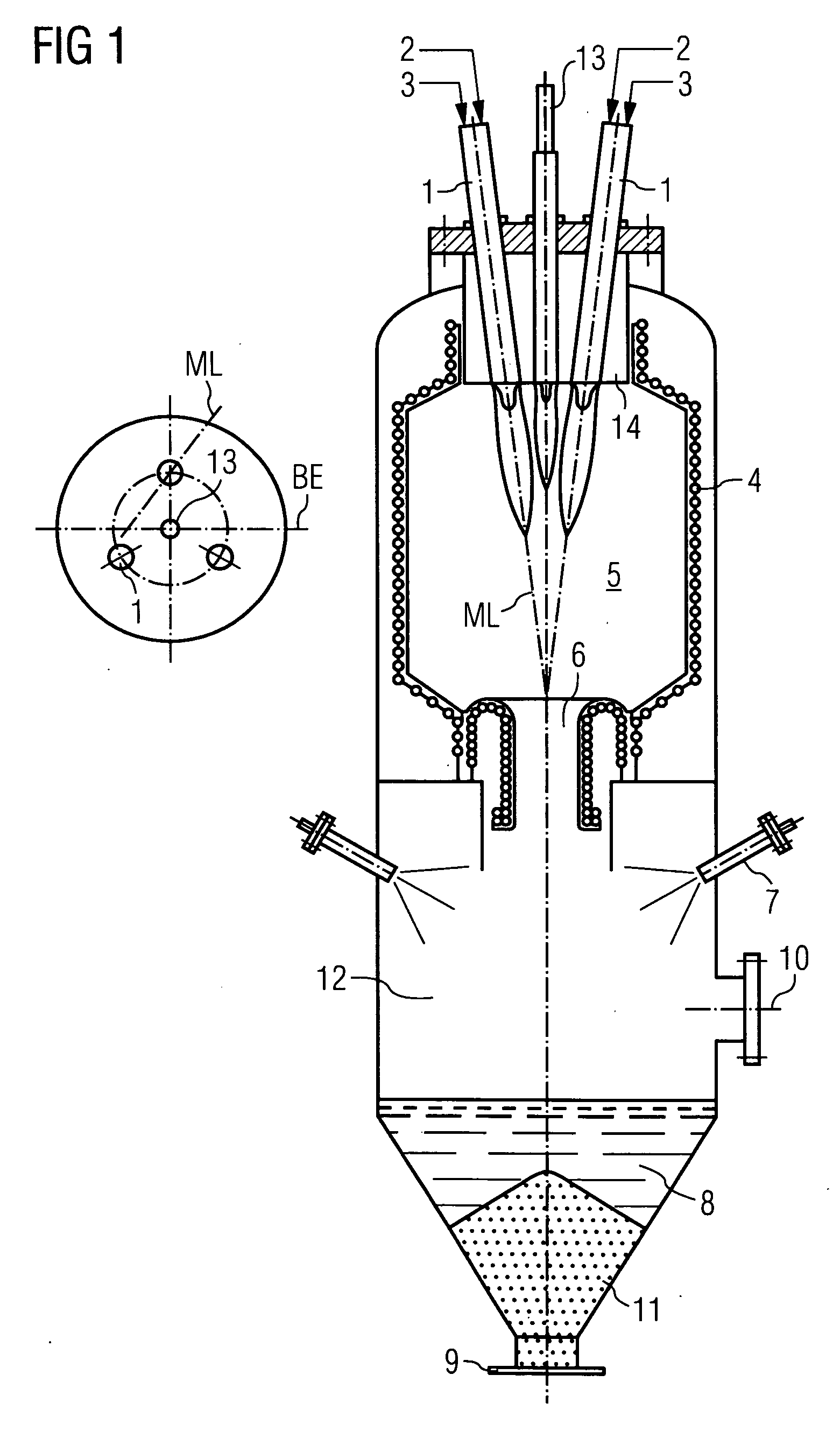
A Multiple Burner Arrangement on a Central Burner Flange According to FIG. 1
[0021]In an entrained flow reactor 300 t / h coal dust 3 with oxygen and steam 2 as the gasification agents are converted to a crude synthesis gas. The gasification temperature is 1,450° C., the gasification pressure 40 bar. An ignition and pilot burner 13 is disposed at the head of the reactor, with three gasification burners 1 symmetrically at a distance of 120°. The coal dust 3 is supplied pneumatically as a coal dust / carrier gas suspension to the gasification burners 1, the conversion takes place in the gasification chamber 5, whose contour is delimited by a cooling screen 4, with the cooling screen being formed by tubes which are welded together in a gastight manner and through which cooling water flows. The hot gasification gas leaves the gasification chamber 5 together with the liquid slag and passes through the crude gas and slag outlet 6 to the quenching chamber 12, into which water is injected by way...
example 2
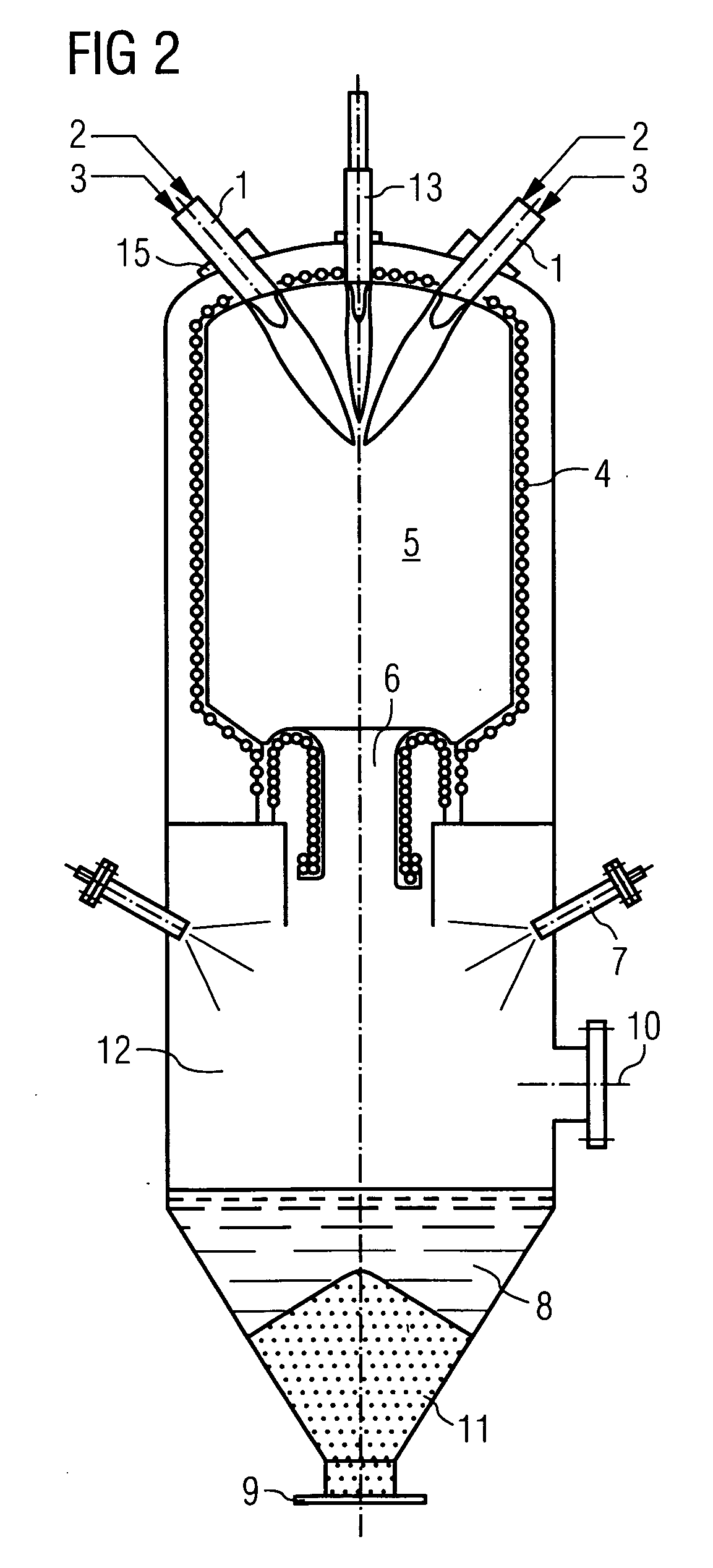
Multiple Burner Arrangement with Individual Flanges According to FIG. 2
[0022]The arrangement corresponds in principle to example 1. If the angle between the reactor axis and the axis of the gasification chamber 1 exceeds a specific value, an arrangement on one burner flange 14 is no longer structurally expedient, because it is too large. In this instance the gasification burners 1 are provided with individual flanges. This measure means that the gasification burners 1 can be disposed in any manner, without restrictions in respect of the selection of the angle between reactor and gasification chamber axes.
example 3
Multiple Burner Arrangement with Individual Flanges According to FIGS. 3 and 4
[0023]The example shows the arrangement of the gasification burners 1 at an angle of 90° to the reactor axis, with the ignition and pilot burner 13 being installed vertically. The gasification burners 1 are positioned opposite each other in pairs, so that the gasification flames are deflected downward toward the reactor axis in the flow direction. The gasification burners 1 are preferably disposed in pairs, in other words 2, 4 or 6 of them. It is also possible to integrate the ignition and pilot burner 12 in one or more gasification burners 1.
[0024]The gasification burners 1 can be supplied with dust-type or liquid fuels, with liquid fuels also including suspensions of liquids such as water or oil with fuels ground to dust or inorganic admixtures.
[0025]It is also possible to position the gasification burner axes at a specific distance from the reactor axis, as shown in FIG. 4. Here a gasification burner is...
PUM
 Abstract
Description
Claims
Application Information