
Cathode subassembly with integrated separator for electrolytic capacitor, and method of manufacture thereof

a technology of electrolytic capacitors and cathodes, which is applied in the direction of capacitors, capacitor housings/encapsulations, capacitor terminals, etc., can solve the problems of partial or complete discharge event, electrical breakdown of incidental gasses present in the completed capacitor, and danger of physical conta

Active Publication Date: 2021-05-25
PACESETTER INC
View PDF14 Cites 0 Cited by
  • Summary
  • Abstract
  • Description
  • Claims
  • Application Information

AI Technical Summary

Benefits of technology

The cathode subassembly design enhances manufacturing efficiency, reduces the risk of device failure, and achieves higher packaging density by ensuring precise alignment and sealing, thereby improving the reliability and performance of stacked electrolytic capacitors.

Problems solved by technology

If the separator is not present as a line of sight barrier between any anode and adjacent cathode, there exists a danger of physical contact, as well as electrical breakdown of any incidental gasses present in the completed capacitor.
Either of these scenarios would result in an undesirable partial or complete discharge event with a high probability of device failure.
The stacked alignment holes result in an undesirably larger overall finished part than would otherwise be required.
The stacked alignment holes also create isolated cavities in the finished part which can lead to gas rich, electrolyte starved regions ripe for latent failure.
The edges of the holes or other features necessarily create more edge length and complexity of shape for each anode, which increases the challenge of removing them flaw-free from the source anode sheet material.

Method used


Image

  • Cathode subassembly with integrated separator for electrolytic capacitor, and method of manufacture thereof
  • Cathode subassembly with integrated separator for electrolytic capacitor, and method of manufacture thereof
  • Cathode subassembly with integrated separator for electrolytic capacitor, and method of manufacture thereof

Examples


Embodiment Construction

[0029]The following detailed description of capacitor and battery designs refers to the accompanying drawings that illustrate exemplary embodiments consistent with these devices. Other embodiments are possible, and modifications may be made to the embodiments within the spirit and scope of the methods and systems presented herein. Therefore, the following detailed description is not meant to limit the devices described herein. Rather, the scope of these devices is defined by the appended claims.

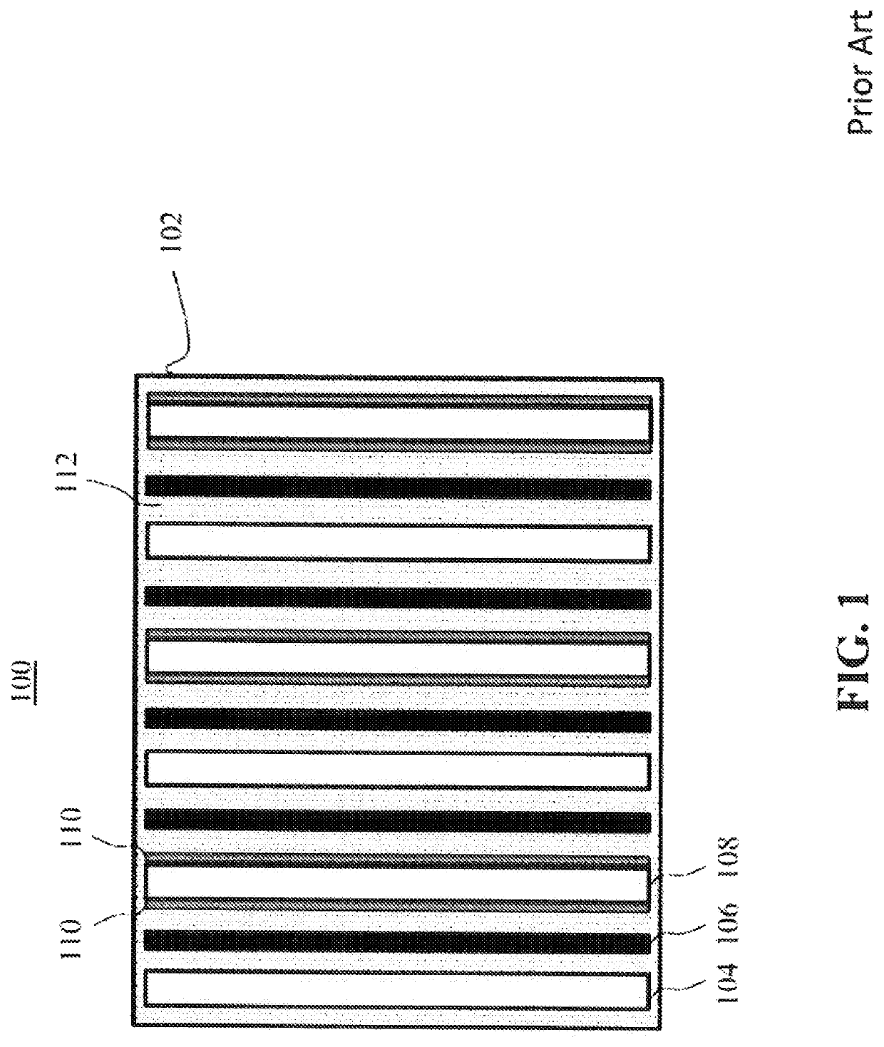
[0030]FIG. 1 illustrates a cross-section view of an electronic component 100. Electronic component 100 includes a housing 102 that contains a plurality of cathodes 104 alternating with a plurality of anodes 108, and separated by a plurality of separators (or spacers) 106. Each anode 108 includes a dielectric material 110 on or around an outer surface of anode 108. Dielectric material 110 may be an oxide that is thermally grown on, or deposited onto, the surface of anode 108. A high-k dielectr...


PUM

PropertyMeasurementUnit
lengthaaaaaaaaaa
perimeteraaaaaaaaaa
voltageaaaaaaaaaa

Abstract

A cathode subassembly for use in an electrolytic capacitor may include a first separator sheet including a surface having first and second regions, where the second region extends from a perimeter of the first region to a first peripheral edge of the first sheet, a second peripheral edge of a second sheet is substantially aligned with the first peripheral edge, a conductive foil is sandwiched between the first and second sheets and disposed within the first region, the first and second sheets are adhered to each other in a sealing region extending from the second region to a region of a surface of the second sheet facing the second region, and the first sheet includes at least one first recessed portion at the first peripheral edge aligned with at least one second recessed portion at the second peripheral edge of the second sheet.

Description

FIELD[0001]The present disclosure relates generally to the field of electrolytic capacitors and batteries.BACKGROUND[0002]Compact, high voltage capacitors are utilized as energy storage reservoirs in many applications, including implantable medical devices. These capacitors are required to have a high energy density, since it is desirable to minimize the overall size of the implanted device. This is particularly true of an Implantable Cardioverter Defibrillator (ICD), also referred to as an implantable defibrillator, since the high voltage capacitors used to deliver the defibrillation pulse can occupy as much as one third of the ICD volume.[0003]Stacked electrolytic capacitors are typically constructed with a plurality of anodes and cathodes, which must be separated by a liquid absorbent insulative material, and are impregnated by an electrically conductive electrolyte. If the separator is not present as a line of sight barrier between any anode and adjacent cathode, there exists a ...

Claims


Application Information

Patent Timeline
Patent Type & Authority Patents(United States)
IPC IPC(8): H01G9/042H01G9/008H01G9/10H01G9/02H01G9/048H01G9/14
CPCH01G9/0425H01G9/008H01G9/02H01G9/048H01G9/10H01G9/14
Inventor BOWEN, DAVID R.HEMPHILL, RALPH JASONSTRANGE, THOMAS F.MCCURRY, TROY L.FERNSTROM, PETER
Owner PACESETTER INC
Learn More