Pneumatic Pressure Regulation Valve

a technology of pneumatic pressure regulation and valve body, which is applied in the direction of fluid pressure control, functional valve types, condensed fuel collection/return, etc., can solve the problems of difficult production of control diaphragms, difficult to produce control diaphragms, and more imprecise overall arrangement, so as to increase the probability of oil droplets being separated and reliable operation

Active Publication Date: 2008-06-19
HENGST WALTER
View PDF10 Cites 48 Cited by
  • Summary
  • Abstract
  • Description
  • Claims
  • Application Information

AI Technical Summary

Benefits of technology

[0064]In order to ensure reliable operation of the pressure regulating valve even at low ambient temperatures, it is furthermore proposed that the preliminary stop structure and/or the control diaphragm or the closing element is provided with a heating device. The heating device can be used to ensure that the preliminary stop structure and/or the control diaphragm or the closing element always comprise(s) such a high temperature that liquid particles from the gas flow cannot freeze thereto and that, thus, any freezing of the pressure regulation valve resulting therefrom is prevented as a whole.
[0065]A further measure for ensuring reliable operation of the pressure regulating valve is to arrange a preseparator, preferably an impingement separator or a prescreen, capturing coarse oil droplets and/or contaminants from the gas flow, upstream of the preliminary stop stru

Problems solved by technology

This known throttle valve is considered to be to disadvantage in that the use of two springs requires a further spring which has to be manufactured and installed in addition.
What is more, this known throttle valve is to disadvantage in that the tolerances of the various components, here the springs, are adding up, with the result that the overall arrangement is more imprecise.
While it is true that this prevents the requirement of a separate second spring, it has turned out that it is difficult to produce the control diaphragms wh

Method used


Image

  • Pneumatic Pressure Regulation Valve
  • Pneumatic Pressure Regulation Valve
  • Pneumatic Pressure Regulation Valve

Examples


Embodiment Construction

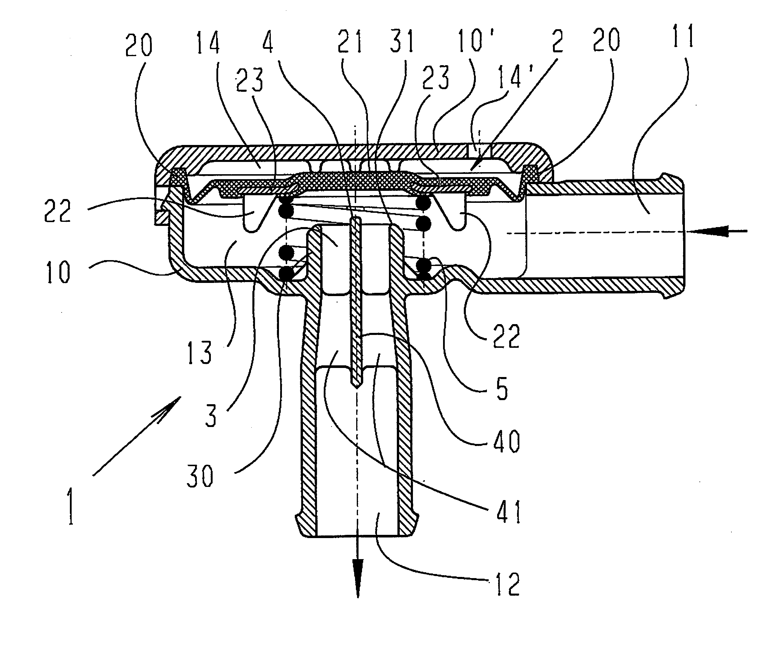
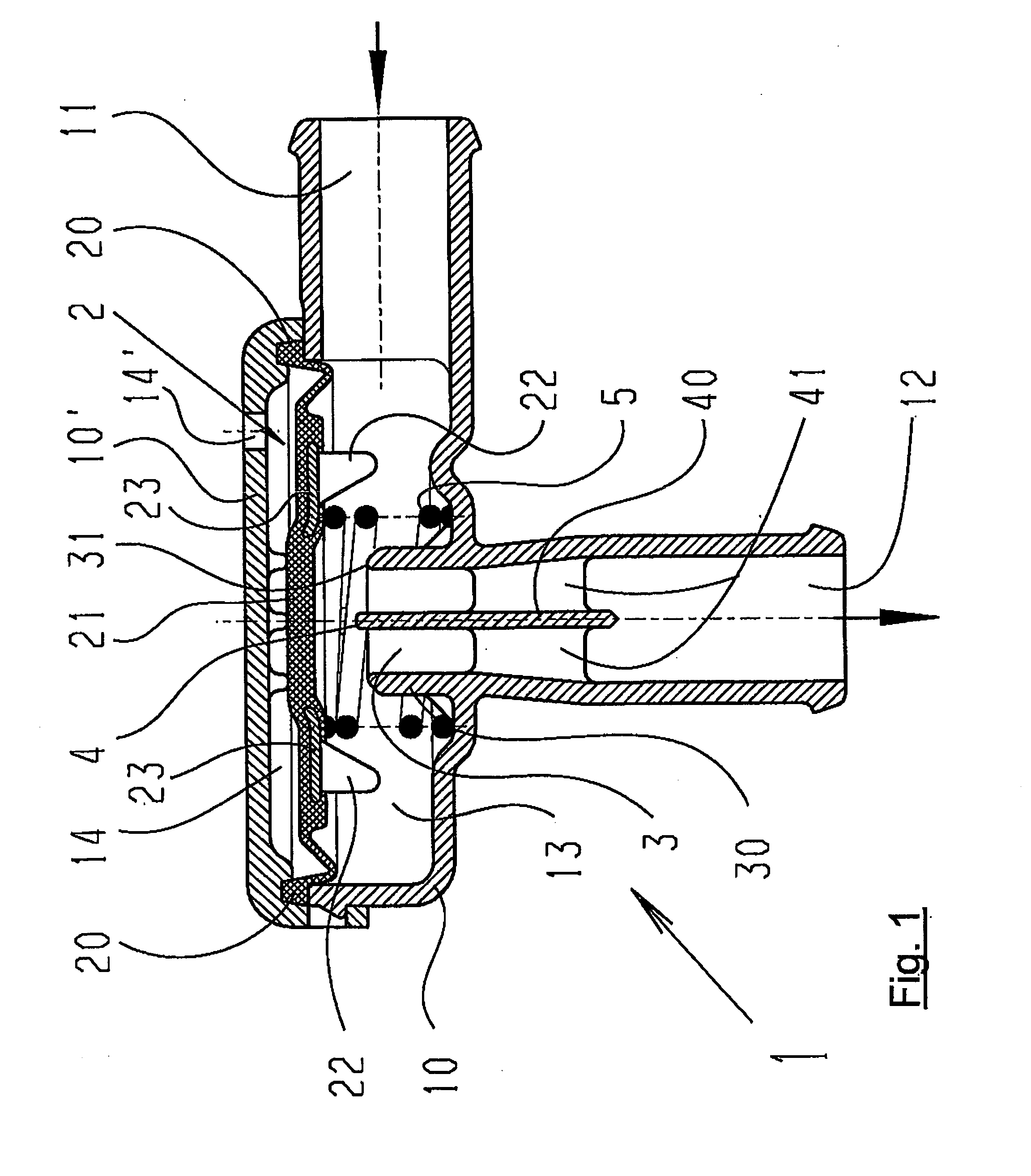
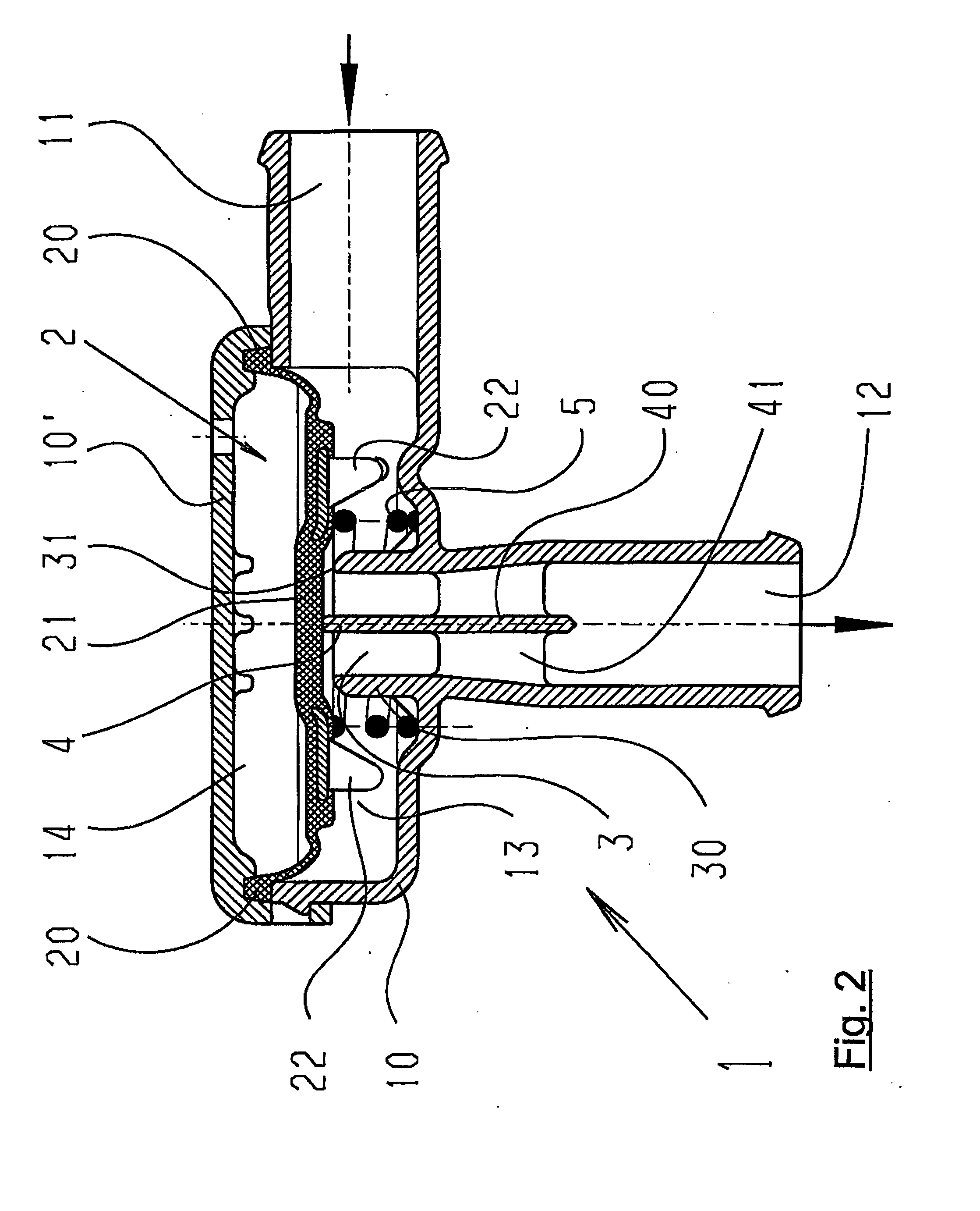
[0117]FIG. 1 is a cross-sectional view of a pressure regulating valve 1. The valve 1 comprises a casing 10 that is closed with a cover 10′ on its upper side. A control diaphragm 2 subdividing the inner region of the casing 10 in a lower chamber 13 and an upper chamber 14 is fixed between the casing 10 and the cover 10′. The upper chamber 14 is connected to the atmosphere via a hole 14′ in the cover 10′, said hole 14′ having a matched cross-section.

[0118]The lower chamber 13 is connected to a gas inlet 11 in the form of a lateral pipe connection piece. For example, the gas inlet 11 can be connected to the crankcase ventilation line of an associated internal combustion engine (not shown).

[0119]Furthermore, the lower chamber 14 is connected to a gas outlet 12 which, in the illustrated instance, points down and also has the form of a pipe connection piece. For example, the gas outlet 12 can be connected to the intake section of an associated internal combustion engine.

[0120]With its upp...


PUM


Abstract

A pneumatic pressure regulating valve, the opening of which can be automatically changed in a pressure-related manner, including a control diaphragm that is subjected to a reference pressure, to the gas pressure as well as to a governor spring, wherein a change in the differential pressure causes an adjustment of the control diaphragm and the latter itself or a closing element actuated by it changes the opening through an outflow cross-section, and wherein a structure that is arranged adjacent to the outflow cross-section on the diaphragm side forms a stop for the control diaphragm or for the closing element in the closed position of said control diaphragm. At least one preliminary stop is arranged in the pressure regulating valve such that, when the control diaphragm is moving in its closing direction, the control diaphragm or the closing element first comes into contact with the preliminary stop and that, when the control diaphragm is moving further in its closing direction, the control diaphragm or the closing element will then, while being subjected to elastic and flexible deformation or being further subjected to elastic and flexible deformation respectively, further reduces the opening and, in a final position, also comes into contact with the stop.

Description

BACKGROUND OF THE INVENTION[0001]The present invention relates to a pneumatic pressure regulating valve arranged in the path of a gas line, the opening of which can be automatically changed by means of said pressure regulating valve in relation to the differential pressure between a reference pressure and one or more gas pressures applied to at least one inlet of said regulating valve, wherein a control diaphragm is provided in the pressure regulating valve, said control diaphragm being, on the one hand, subjected to the reference pressure and, on the other hand, to the gas pressure or gas pressures as well as to a governor spring, wherein a change in the differential pressure between the regions adjacent to the control diaphragm causes an adjustment of the control diaphragm and the control diaphragm itself or a closing element actuated by the control diaphragm increases or reduces the opening through an outflow cross-section of the pressure regulating valve, and wherein a structure...

Claims


Application Information

Patent Timeline
IPC IPC(8): F16K31/12F16K7/17G05D16/06
CPCF16K7/17G05D16/0641G05D16/024Y10T137/7762Y10T137/785F16K15/144
Inventor MEINIG, UWEMAY
Owner HENGST WALTER
Why Eureka
Try Eureka