Conveyor Device for Containers Such as Preforms

a technology for conveying devices and containers, applied in the direction of mechanical conveyors, conveyor parts, transportation and packaging, etc., can solve the problems of ejection of preforms from the slide, high cost, and large dimensions, and the assembly of the feed device is generally metallic, and cannot solve the problem of ejection of preforms out of the slide,

Inactive Publication Date: 2008-06-19
SIDEL PARTICIPATIONS SAS
View PDF9 Cites 21 Cited by
  • Summary
  • Abstract
  • Description
  • Claims
  • Application Information

AI Technical Summary

Benefits of technology

[0016]Such an arrangement of endless belts substantially rigid in the transverse direction and disposed vertically proves to be particular advantageous for the variant embodiments they allow. Thus, it becomes possible to provide for at least one conveyor to be mounted on a transversely movable frame in such a way that the separation distance between the two substantially parallel lines can be adjusted according to the diameter of the body of the containers and to the diameter of the collar of the containers. It is then desirable that the two conveyors should be mounted on respective frames that are transversely movable in a symmetrical manner in such a way that the trajectory of movement of the axis of the containers remains aligned with the devices situates upstream and / or downstream. These arrangements allow a same conveyor device to be adapted, in a simple manner, to the processing of containers having different dimensional characteristics.
[0017]As clearly apparent from the above explanations, the conveyor device according to the invention can be applied for the conveying of many types of containers equipped with a collar at the base of the neck. A preferred application, even though not exclusive, relates to the feeding of preforms at the entrance of an installation for manufacturing containers, the preforms being delivered in a vertical position with the neck uppermost, the preforms being moved by positive driving on a path which can be substantially horizontal. Said disadvantages of gravity-driven devices can thus be avoided: the device according to the invention does not necessitate especially high premises for its installation and it can be disposed at the height of a man such that all of the safety accessories necessary for personnel working at height can be eliminated.

Problems solved by technology

This result of this is that the feed device assembly, generally metallic, is of very high cost and has large dimensions, at ground level and, in particular, vertically.
It can also be added that the preforms, in a substantially vertical position, are supported on the two ramps of the inclined slide only by two points of their collar and this mediocre support causes the preforms to progress on the slide in an irregular and rocking manner, which proves to be disadvantageous (risk of jamming in the slide or of ejection of preforms out of the slide).
Even though this known device meets the expectations of users with regard to low manufacturing cost and low overall size, in particular vertical size, it does not however solve certain problems which arise in the phase of feeding preforms, in particular with regard to the elimination of undesirable preforms (defective preforms, preforms nested in each other, etc.).

Method used


Image

  • Conveyor Device for Containers Such as Preforms
  • Conveyor Device for Containers Such as Preforms
  • Conveyor Device for Containers Such as Preforms

Examples


Embodiment Construction

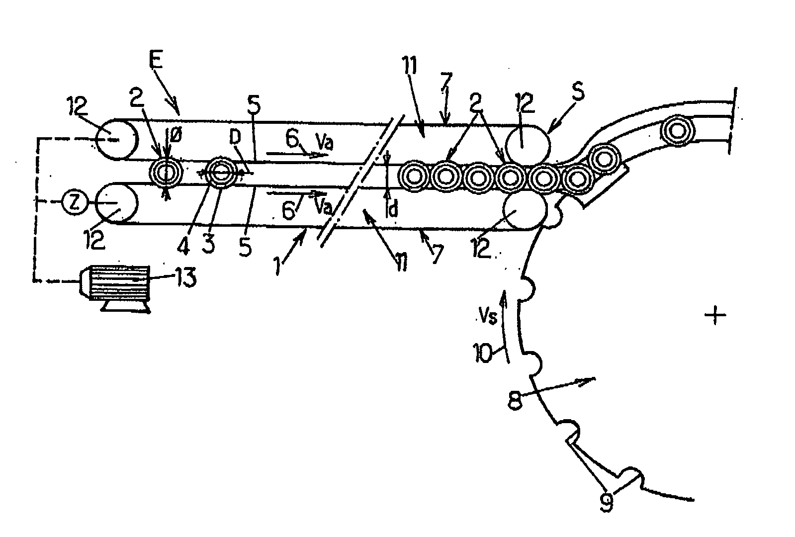
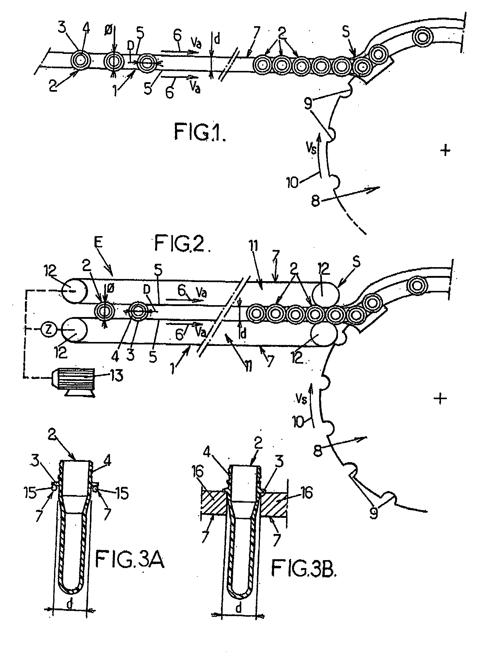
[0025]Referring firstly to FIG. 1, this figure shows, in a very diagrammatic manner, a conveyor device, designated in its entirety by the reference 1, able to move, substantially rectilinearly and substantially horizontally, containers 2 such as performs, in particular made of thermoplastic material such as PET, provided with a collar 3, at the base of their neck 4. The conveyor device 1 comprises two lines 5, moving as shown by the arrows 6, of at least one endless link denoted in its entirety by the reference 7. These two lines 5 are substantially parallel and substantially horizontal and are derived in the same direction (arrows 6) and substantially at the same speed Va. Moreover, these two lines 5 are separated from each other by a distance d greater than the diameter D of the body and / or of the neck 4 of the containers 2 and less than the diameter Φ of the collar 3 of the containers 2 such that the containers 2 are supported in a substantially vertical position on the two lines...


PUM


Abstract

A linear, horizontal conveyor device for containers which are equipped with a collar at the base of the neck thereof. The invention includes two conveyors including endless links, which are each equipped with two parallel, mobile lines which face one another and which are driven in the same direction and at the same speed. The aforementioned lines are separated from one another by a distance that is greater than the diameter of the body of the containers and less than the diameter of the collars thereof. At least one conveyor includes a short segment that can be moved transversely outwards, such that the space between the two facing lines becomes greater than the diameter of the collar and the container falls.

Description

FIELD OF THE INVENTION[0001]The present invention relates generally to the conveying or transfer of containers and, more specifically, it relates to improvements applied to conveyor devices able to move, substantially rectilinearly and substantially horizontally, containers, in particular those made of thermoplastic material, comprising a collar at the base of their neck.BACKGROUND OF THE INVENTION[0002]In particular, in installations for the manufacture of containers such as bottles and for the packaging of products in such containers, the containers are moved by transfer or conveyor devices which are of many types (endless belt conveyors, notched wheels or wheels with arms, endless conveyors with turntables, pulsed air slides, inclined slides with movement by gravity, etc.).[0003]In particular, at the entrance of an installation suitable for the manufacture of containers from preforms, the preforms must be fed one after the other without discontinuity and must be pushed in order t...

Claims


Application Information

Patent Timeline
Patent Type & Authority Applications(United States)
IPC IPC(8): B65G15/14
CPCB65G15/105B65G51/035B65G15/14
Inventor CHARPENTIER, ALAIN
Owner SIDEL PARTICIPATIONS SAS
Why Eureka
Try Eureka