Check patentability & draft patents in minutes with Patsnap Eureka AI!

Bill depositing/withdrawing apparatus and method of controlling the same

Inactive Publication Date: 2008-06-19
HITACHI OMRON TERMINAL SOLUTIONS CORP
View PDF7 Cites 33 Cited by
  • Summary
  • Abstract
  • Description
  • Claims
  • Application Information

AI Technical Summary

Benefits of technology

[0015]The invention has been thought of in view of the problems described above and has its object to provide a bill depositing / withdrawing device, in which it is possible to change a posture of a bill storage section at the time of money depositing / withdrawing and at the time of feeding and stacking and a user does not feel a fear when charging a bill or bills, or the like, and a method of controlling the bill depositing / withdrawing device, thus improving a user's degree of satisfaction.
[0018]According to the invention, it is possible to provide a bill depositing / withdrawing apparatus, which can change a posture of a bill storage section at the time of depositing / withdrawing and at the time of feeding / stacking and prevents a user from feeling a fear when charging a bill or bills, and a method of controlling the bill depositing / withdrawing apparatus, thus enabling improving a user's degree of satisfaction.

Problems solved by technology

When fed into the device, such bill or bills are sometimes skewed much or torn to cause jam generated on a bill conveyance path according to a state of conveyance.
With the cash slot, which affords depositing / withdrawing of a bill or bills horizontally, as in the JP-A-10-181928 described above, however, ends of bills cannot be aligned due to gravity when bills are charged.
Therefore, bills in an unevenly aligned state are frequently taken into the device, which sometimes causes jam in conveyance, and thus reduction in bill jam at the time of feeding presents an important problem.
Therefore, in some cases, a bill or bills, such foreign bill or bills, which are small in size, are left in the cash slot, so that a subsequent transaction is made impossible.
In such case, handling of the device cannot help but be reserved, so that prevention of leaving a bill or bills is an important problem.
Therefore, there is caused a problem that a user is psychologically afraid to insert a hand, and so it is an important task to make a user interface at the cash slot friendly to a user.

Method used


Image

  • Bill depositing/withdrawing apparatus and method of controlling the same
  • Bill depositing/withdrawing apparatus and method of controlling the same
  • Bill depositing/withdrawing apparatus and method of controlling the same

Examples


Embodiment Construction

[0040]An embodiment of the invention will be described hereinafter with reference to the drawings.

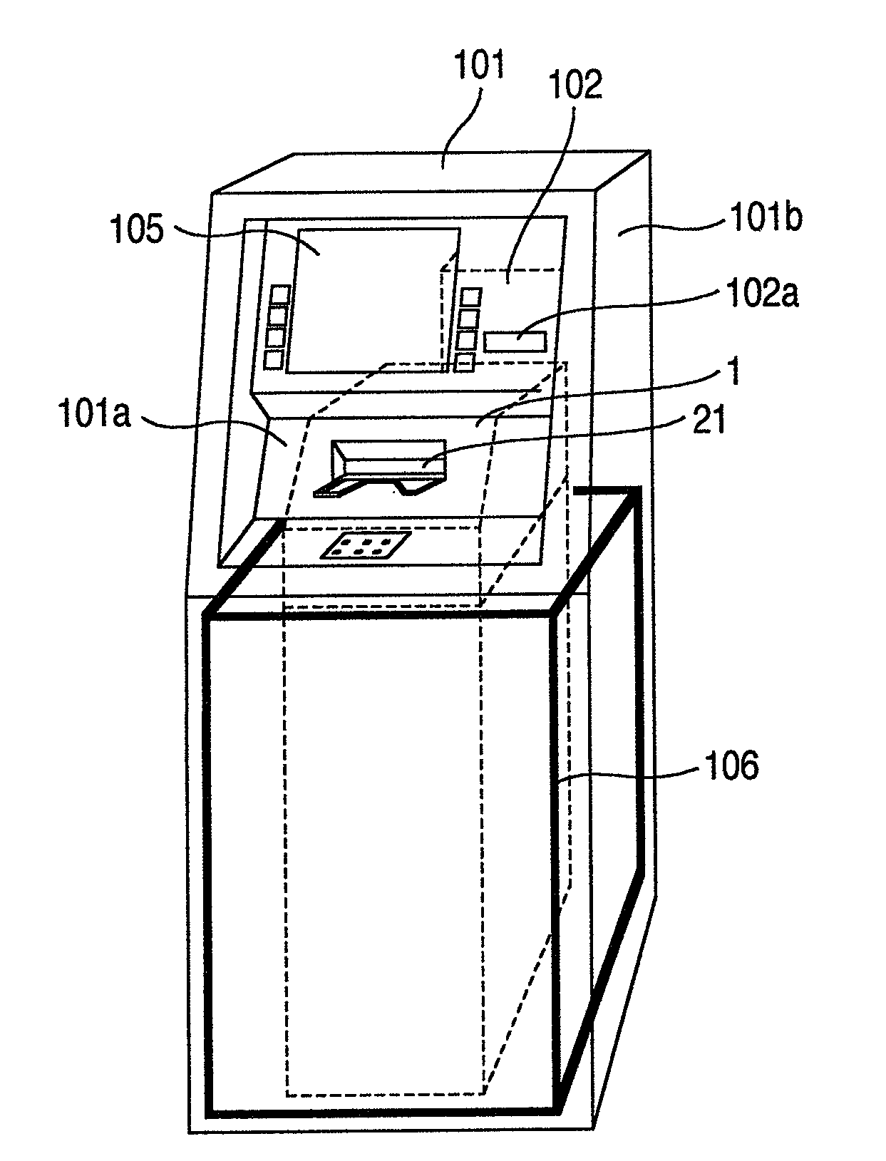
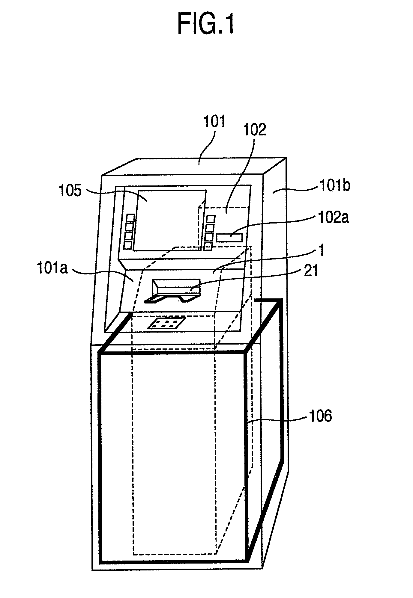
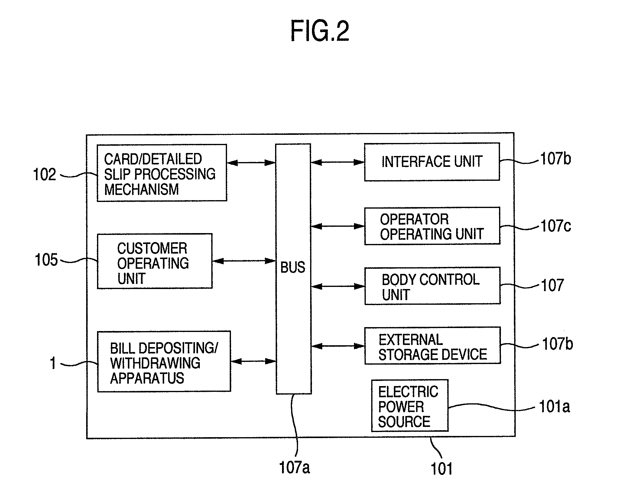
[0041]FIG. 1 is a perspective view showing an appearance of an automated transaction machine 101.

[0042]The automated transaction machine 101 comprises a housing 101b. A customer operating unit 105 is provided in an upper portion of the housing 101b and a card / detailed slip processing mechanism 102 is provided on the left. The customer operating unit 105 displays and inputs contents of transaction. The card / detailed slip processing mechanism 102 is communicated with a card slot 102a provided on an upper, front plate 101a to process a transaction card of a customer to print a detailed slip of transaction to discharge the same.

[0043]The upper, front plate 101a of the automated transaction machine 101A is provided with a cash slot (bill slot) 21. A bill depositing / withdrawing apparatus 1 for processing bills is provided in the automated transaction machine 101.

[0044]A bill storage section d...


PUM


Abstract

A bill depositing / withdrawing apparatus having a cash slot for charging / discharging a bill or bills, comprises: a bill storage section provided inwardly of the cash slot in the apparatus to store a bill or bills, and posture changing means that changes the bill storage section to a money depositing / withdrawing posture, in which a bill or bills are received from and paid to a user through the cash slot, and to a feeding / stacking posture, in which a bill or bills are fed into the apparatus and stacked in the bill storage section, and wherein a bill or bills stored in the bill storage section are caused to project toward a user when the money depositing / withdrawing posture is assumed.

Description

BACKGROUND OF THE INVENTION[0001]The present invention relates to a bill depositing / withdrawing apparatus, which handles, for example, a bill or bills.[0002]Conventionally, a bill depositing / withdrawing apparatus is mounted in an automated transaction machine used in financial institutions, and the like. The bill depositing / withdrawing apparatus comprises a cash slot for allowing a user to deposit / withdraw a bill or bills, a bill discriminator for discrimination of a bill, and a bill conveyance path, which passes the bill discriminator and conveys a bill or bills. Also, the bill depositing / withdrawing apparatus comprises a combination of respective units, such as a temporary stocker for temporarily storing a deposited bill or bills, a deposit box for storing a deposited bill or bills, a withdrawal box, from which a bill or bills for withdrawal are fed, a recycle box for storing and feeding a bill or bills for deposits and withdrawals, a reject box for storing a bill or bills, which ...

Claims


Application Information

Patent Timeline
IPC IPC(8): G07D11/00
CPCG07D11/0018G07F19/20B65H2408/13G07F19/203G07F19/202G07D11/14B65H31/3027G07F19/00G07D9/00
Inventor YOKOI, TOSHINORIKATO, RIICHIKADOWAKI, MINORUSHIBATA, SHINJIFUJITA, JUNJI
Owner HITACHI OMRON TERMINAL SOLUTIONS CORP
Features
  • R&D
  • Intellectual Property
  • Life Sciences
  • Materials
  • Tech Scout
  • Unparalleled Data Quality
  • Higher Quality Content
  • 60% Fewer Hallucinations
Learn More