Deflection device for a stream body

a technology of a refueling hose and a deflection device, which is applied in the field of aeronautics, can solve the problems of strong turbulence that can arise downstream of the stream body, and achieve the effects of reducing the length of the portion, and reducing the instabilities of the refueling hos

Active Publication Date: 2008-06-19
AIRBUS OPERATIONS GMBH
View PDF17 Cites 4 Cited by
  • Summary
  • Abstract
  • Description
  • Claims
  • Application Information

AI Technical Summary

Benefits of technology

[0017] By means of bending in a way that is essentially vertical to the local stream direction, it can be accomplished that the maximum effect may be achieved. The effect of faces on streams depends on the size of the face cross section, which is vertical to the local stream direction. In the case of faces, which are bent in a way that is essentially vertical to the local stream direction, it can be ensured that the maximum face area of the deflection device is available as effective area. Thus, an efficient effect can be achieved.
[0018] According to a further exemplary embodiment of the present invention, a method for reducing hose-out instabilities of a refueling hose dragged downstream of a refueling pod of a tanker aircraft is indicated. Herein, hose-out instability means that turbulences stimulate the dragged refueling hose to perform vibrations, which can build up to strong movements of the refueling hose. The refueling pod is streamed against in a stream direction. By means of deflection of a stream angular to the stream direction, the length of a region of the refueling hose, which is located downstream of the refueling pod during flight, is influenced. The deflection essentially occurs in stream direction at the end of the refueling pod.
[0019] In an advantageous manner, the length of a portion of the refueling hose, which is affected by the turbulences, is influenced by the deflection of the stream. The shorter the length of the portion, the more stable the movement of the hose. A refueling process can be simplified and possibly accelerated by means of the stable position of the hose.

Problems solved by technology

If the body streamed against is a stream body having a blunt end, strong turbulences can arise downstream of the stream body due to the slipstream.

Method used


Image

  • Deflection device for a stream body
  • Deflection device for a stream body
  • Deflection device for a stream body

Examples


Embodiment Construction

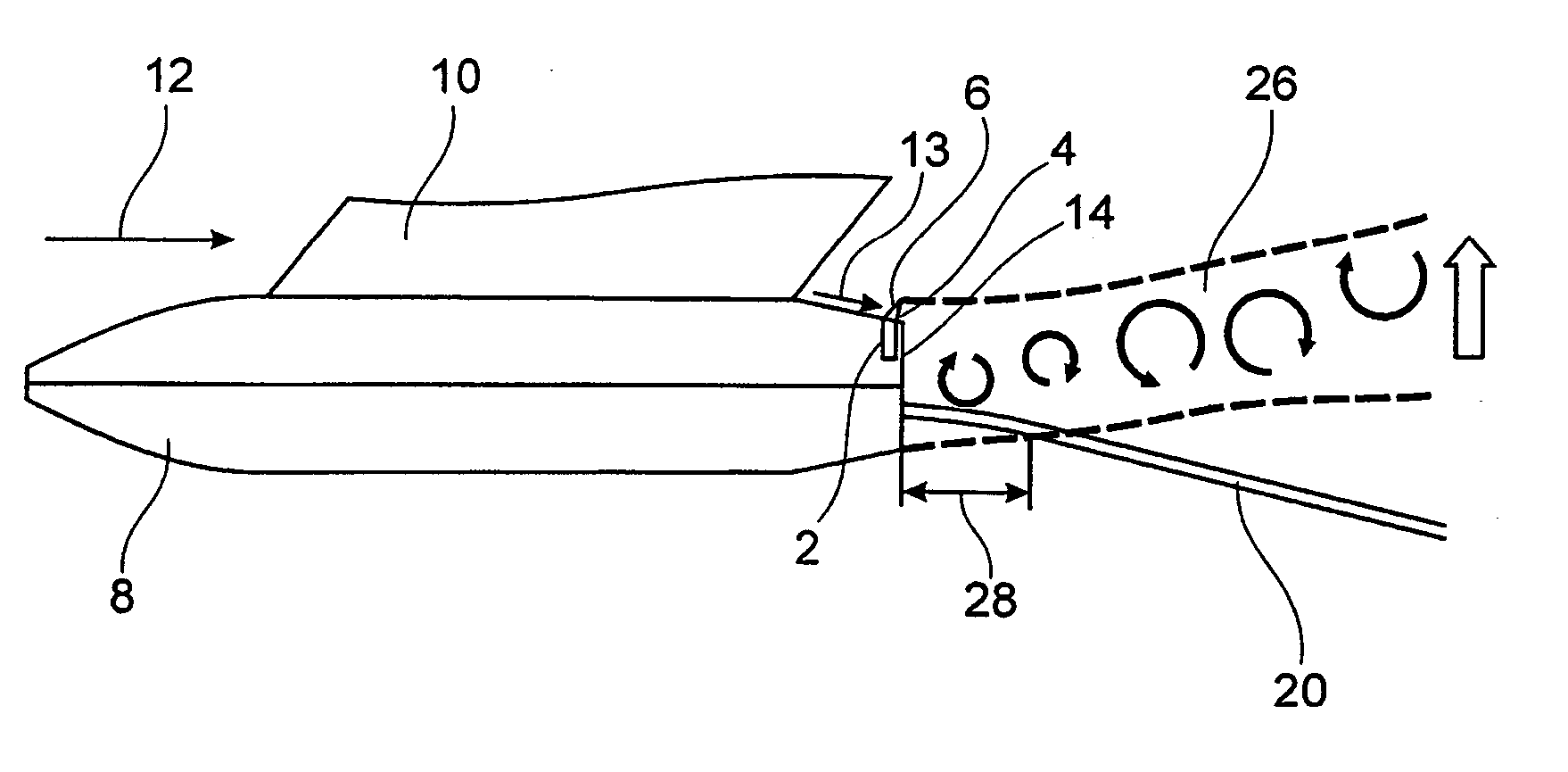
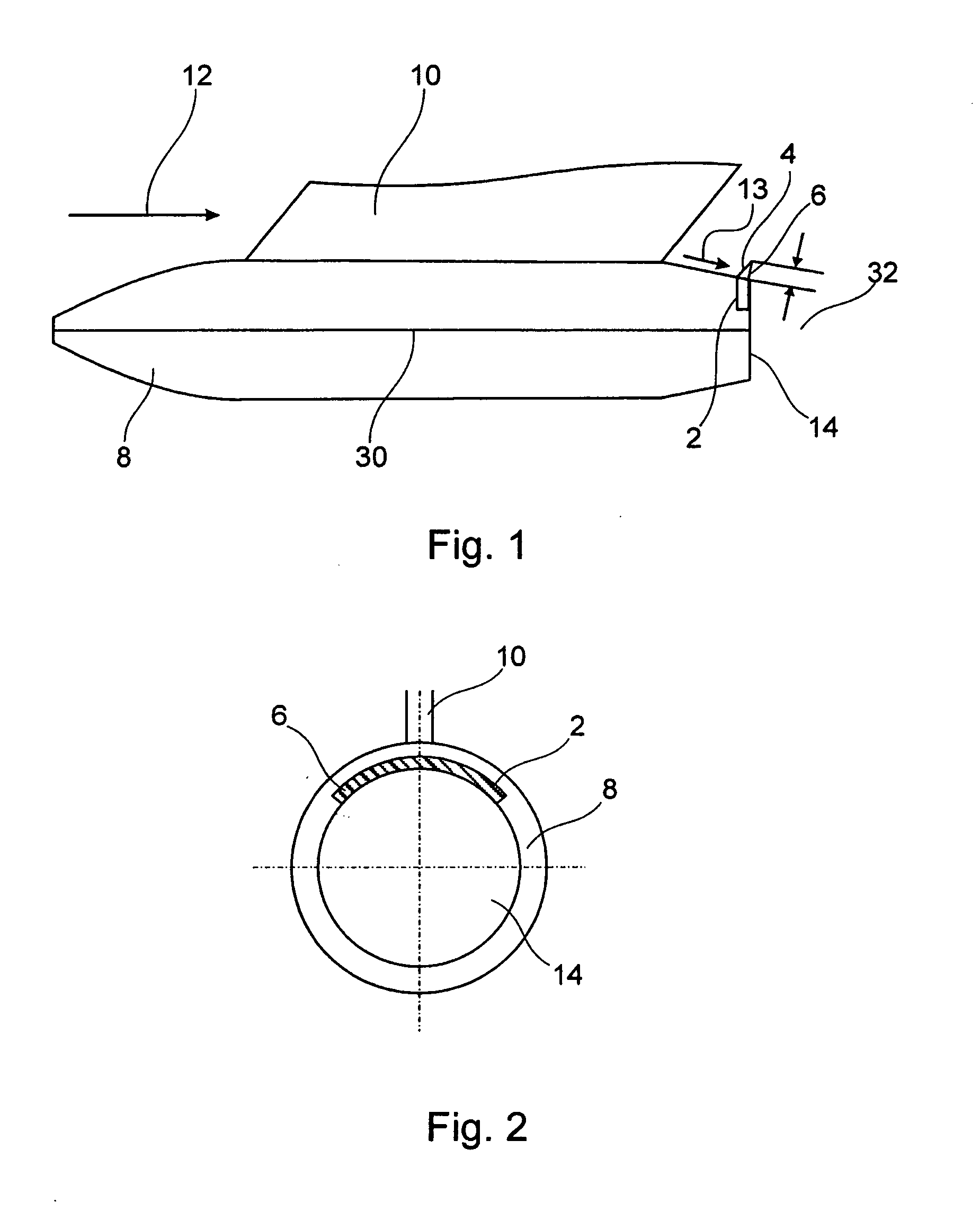
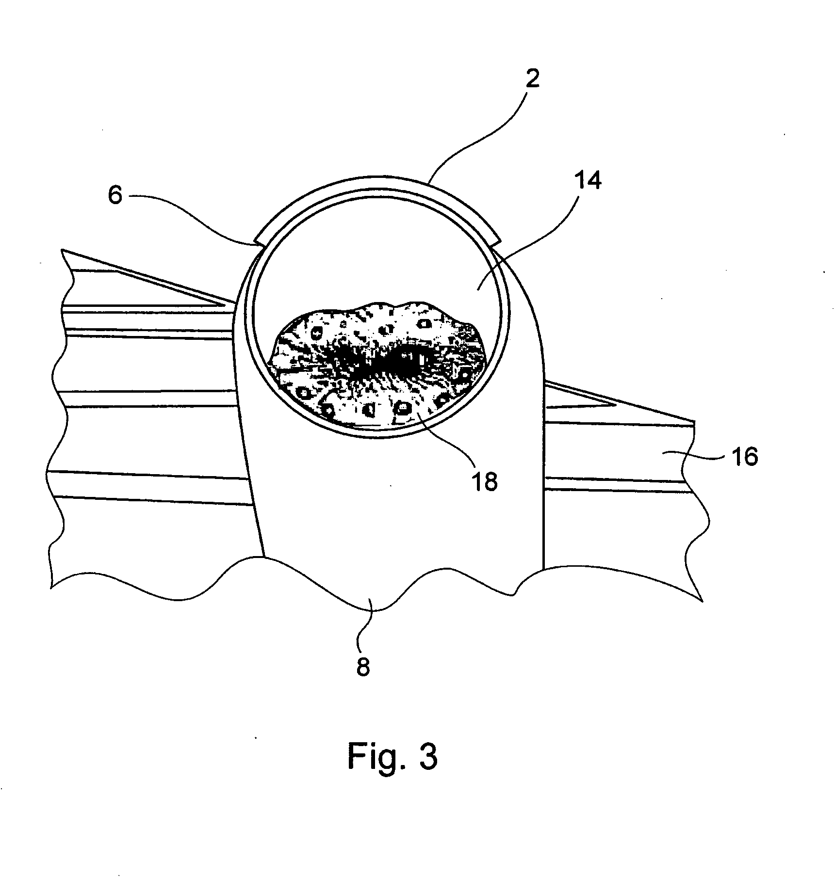
[0028]FIG. 1 shows an elementary two-dimensional side view of a refueling pod with the deflection device mounted in the rear region, according to an exemplary embodiment of the present invention. The refueling pod 8 is a stream body, whose front quarter is constructed to form a point. When moving, the stream body is subjected to an airflow in the stream direction 12. The front end of the refueling pod 8 eases a motion against the stream direction 12 due to the pointed construction shape, which corresponds to a streamlined shape. Air, through which, for example, the stream body 8 is moving, is displaced by the stream body in its front quarter and streams closely along the stream body toward the rear end. The stream body is an axially symmetric body with the rotation axis 30. In the middle region, in connection with the front quarter, the refueling pod 8 has a constant diameter. In the rear quarter, the up to this point constant diameter tapers until it forms a blunt region 14, which ...


PUM


Abstract

The present application describes to a deflection device, for example, for a blunt stream body. The deflection device has an edge, which, for example, can be mounted to the stream body. In an advantageous manner, the deflection device allows an influencing of the slipstream in such a way that turbulences, which are connected with the slipstream and form downstream of blunt stream bodies, have as little influence as possible on the dragged object in order to avoid the formation of building-up motions of the dragged object, which lead to instabilities.

Description

REFERENCE TO RELATED APPLICATIONS [0001] This application claims the benefit of the filing date of United States Provisional Patent Application No. 60 / 588,612 filed Jul. 16, 2004, and of the German Patent Application No. 10 2004 034 367.5 filed Jul. 16, 2004, the disclosure of which is hereby incorporated herein by reference.FIELD OF THE INVENTION [0002] The present invention relates to the aeronautics of, for example, an aircraft. In particular, the present invention relates to a deflection device for influencing a slipstream of a body subjected to an airflow as well as to a corresponding method. BACKGROUND OF THE INVENTION [0003] In aviation, it is frequently necessary to drag bodies having arbitrary properties downstream of aircraft in flight. This can have various reasons. In the case of measurements of the atmosphere, for example, probes have to be dragged through the air in order to obtain meteorological data. Alternatively, in the case of tanker aircraft during flight, refuel...

Claims


Application Information

Patent Timeline
Patent Type & Authority Applications(United States)
IPC IPC(8): B64C9/00B64D39/00
CPCB64C5/00B64D39/00B64C23/00B64C7/00
Inventor LEJEAU, DAMIENAUMANN, PETRASCHWETZLER, DETLEV
Owner AIRBUS OPERATIONS GMBH
Why Eureka
Try Eureka