
Holding device

a technology of holding device and holding plate, which is applied in the direction of snap fasteners, manufacturing tools, rod connections, etc., can solve the problems of difficult access for maintenance personnel, limited ability to freely position the holding plate, and visible holes, etc., and achieves the effect of facilitating the deinstallation of components

Inactive Publication Date: 2008-06-19
AIRBUS OPERATIONS GMBH
View PDF14 Cites 19 Cited by
  • Summary
  • Abstract
  • Description
  • Claims
  • Application Information

AI Technical Summary

Benefits of technology

[0005]Among other things, it may be an object to at least partly solve the problems, as mentioned above, which problems are associated with known holding devices, and to propose a corresponding holding device. It may be a further object to propose a method by means of which method, deinstallation of components may be achieved more easily.
[0009]According to an embodiment, moving the holding device from the holding mode to the release mode may be achieved by additional manual action of force. Holding may be released by the additional manual action of force; in this case, release is, however, particularly easily and quickly.
[0012]In one embodiment, the magnetic key may comprise a magnetic element and a cover that covers the magnetic element, preferably in the form of a glove. By using this glove with an integrated magnet, maintenance personnel have a simple tool that does not damage the component surfaces, some of which are easily damaged, by means of which tool not only the magnetic force, but also the pressure force may be exerted gently in order to overcome the holding action.
[0014]Furthermore, the holding device is further improved with the incorporation of a decoupling element for the holding device. By using the decoupling element, mechanical oscillations, such as sound waves acting on the components, may be attenuated where the oscillations may be transmitted from one component to the other. The decoupling element may, for example, be a rubber bearing or a rubber sleeve. In this way, the holding device may be particularly advantageously sealed off from dirt and humidity, and in this way, the spring element located in the holding device may be protected from corrosion. In an alternative, the decoupling element itself may be a spring element in the form of a metal spring. Furthermore, the decoupling element may be designed so as to be in one piece with the holding device. The decoupling element may also be designed as a separate component so that it may be coupled to the holding device, or to one of the components, for example, by plugging on or plugging in.

Problems solved by technology

In such arrangements, the ability to freely position the holding devices is very limited for aesthetic and practical reasons, because the above-mentioned access needs to be ensured at all times, and as little of the holding technology as possible is to be visible.
The presence of aesthetically displeasing, i.e. visible holes, is a problem that is often encountered in this context.
Furthermore, accessibility by maintenance personnel may be difficult as a result of gaps or seals because the components completely or partly cover the holding devices to be undone, thus rendering the holding devices invisible to maintenance personnel.

Method used


Image

  • Holding device
  • Holding device
  • Holding device

Examples


Embodiment Construction

[0021]The examples described and drawings rendered are illustrative and are not to be read as limiting the scope of the invention as it is defined by the appended claims.

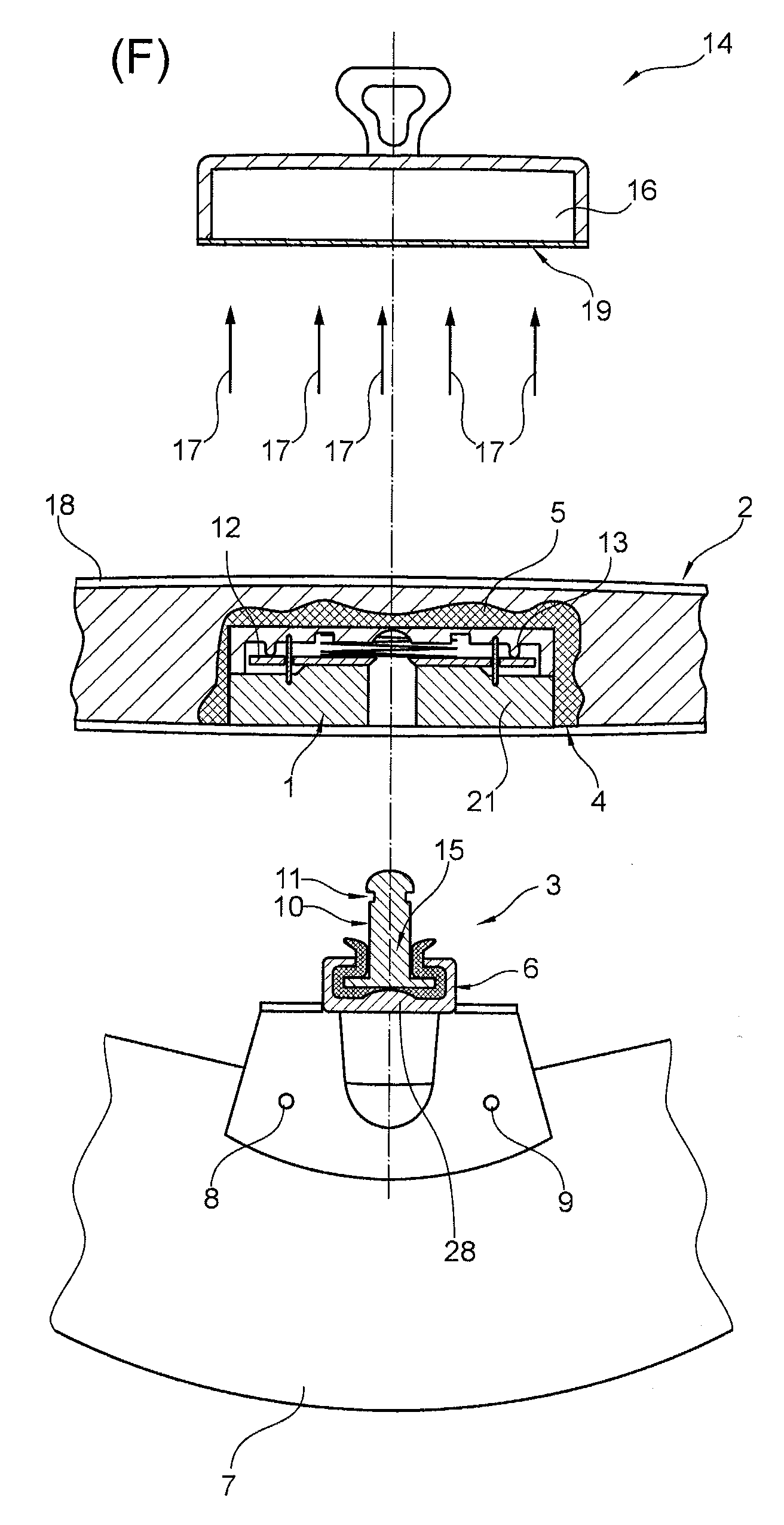
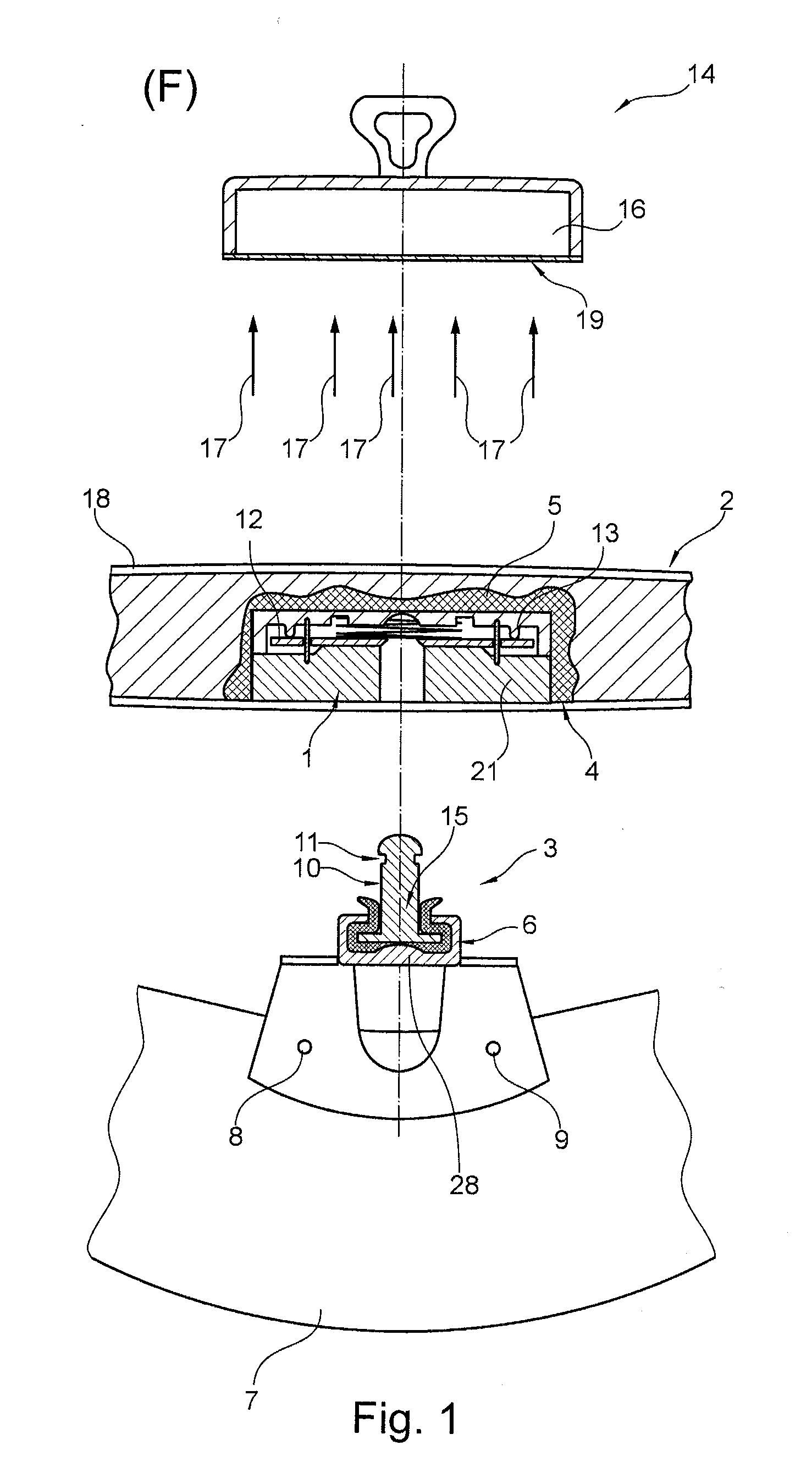
[0022]FIG. 1 shows a holding device 1 for holding a first component 2 to a second component 3. In this arrangement, the holding device 1 is glued, using an adhesive 5, in a recess 4 of the first component 2, for example, the trim of the interior of an aircraft, service flaps, or flaps of electrical components that are inaccessible to passengers. Generally speaking, gluing on may also be used. The second component may be a holder in one example (not depicted). A decoupling element 6 in the form of a rubber bearing is placed on second component 3. The second component may be fastened to a further component 7, an aircraft frame element, using holes 8, 9 and by using screw connections (not shown in the diagram).

[0023]The holding device 1 may be coupled to the second component, which is a holder, in one example. For this...


PUM

PropertyMeasurementUnit
Timeaaaaaaaaaa
Forceaaaaaaaaaa
Magnetic forceaaaaaaaaaa

Abstract

A holding device for holding a structural component for aircraft to a further structural component; may be coupled to one of the components and is moved from a holding mode, where the first component is held to the second component by the holding device, to a release mode using a magnetic force. Furthermore, a method for deinstalling two components is disclosed, where carrying out deinstallation merely requires pressing a first component against a second component, and placing a magnetic key on or over one of the components in the region of the holding device, where at least some method-related steps may take place at substantially the same time.

Description

REFERENCE TO RELATED APPLICATION[0001]This application claims the benefit of the filing date of German Patent Application No. 10 2006 060 074.6 filed Dec. 19, 2006 and of U.S. Provisional Patent Application 60 / 870,627 filed Dec. 19, 2006, the disclosures of which applications are hereby incorporated herein by reference.FIELD OF THE INVENTION[0002]The field relates to a holding device for holding components, a deinstallation method for components that comprise holding devices, and to an aircraft, as well as to a set comprising the holding device.BACKGROUND OF THE INVENTION[0003]As is generally known, components, for example, in the form of cabin components, for example, in the form of ceiling- or wall elements, are held to other components, i.e., generally to structural components, but also to other holding devices, the majority of which are complementary, by means of holding devices, for example, in the form of screws, pins, bushes, hooks or dowels. In such arrangements, the holding...

Claims


Application Information

Patent Timeline
IPC IPC(8): B25B11/00
CPCE05B47/0038E05B47/0045E05B65/006F16B5/01F16B5/0657F16B21/16Y10T24/45775Y10T29/49822Y10T29/49815Y10T403/32475Y10T29/49824Y10T403/32483F16B2001/0035Y10T292/438Y10T292/0817F16B2200/83
Inventor ROTH, INGO
Owner AIRBUS OPERATIONS GMBH
Learn More