Vision analysis system for a process vessel

a technology for visual analysis and process vessels, which is applied in the direction of television systems, liquid/fluent solid measurement, instruments, etc., can solve the problems of reducing the ability of vision monitoring, affecting the culture of oxygen, and causing the vessel to have a large amount of foam in the headspace, etc., to achieve the effect of minimizing costs and expanding vision monitoring capabilities

Inactive Publication Date: 2008-06-19
POLLACK LAB
View PDF55 Cites 25 Cited by
  • Summary
  • Abstract
  • Description
  • Claims
  • Application Information

AI Technical Summary

Benefits of technology

[0015]The probe is sealed from the process liquid via an elongate protective shroud and various components of the probe are interchangeable. For example, the shroud permits movement of components, such as the camera or other sensors, to d...

Problems solved by technology

Problems can arise with respect to the injection of gas into the process liquid.
For example, if the size, volume, quantity, or injection rate of bubbles and/or parameters, such as bubble size versus volume, is too great, a significant quantity of the bubbles will reach the surface of the process liquid without being absorbed and will create an undesirable amount of foam in the headspace of the vessel.
The presence of too much foam can effectively close off the upper surface of the process liquid, thereby starving the culture of oxygen, and/or can clog filters.
Problems can also occur if the size, volume, quantity, or injection rate of bubbles and/or parameters, such as b...

Method used


Image

  • Vision analysis system for a process vessel
  • Vision analysis system for a process vessel
  • Vision analysis system for a process vessel

Examples


Embodiment Construction

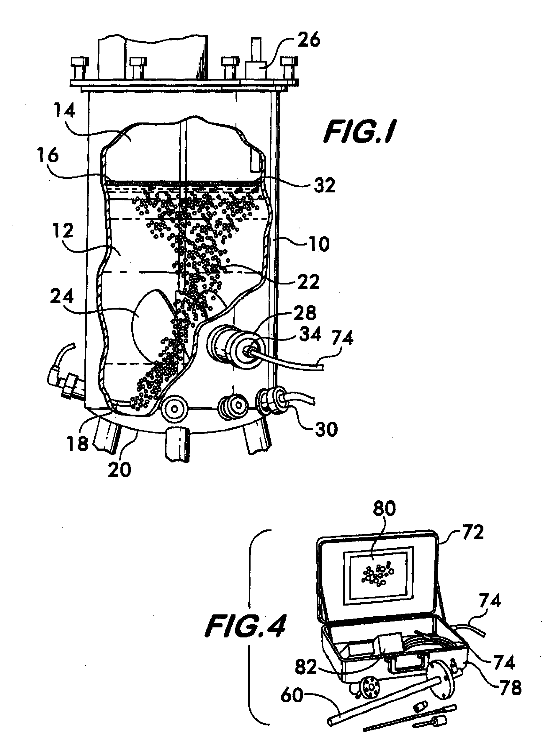
[0026]A vessel, tank, or vat 10 is illustrated in FIG. 1. The vessel 10 can be a sealed vessel that is closed at its upper and lower ends, or an unsealed vessel that has, for instance, an open upper end. For purposes of example, the vessel 10 can be a bioreactor or microbial fermenter used in the production of biopharmaceuticals, enzymes or other biotechnology derived compounds. The vessel according to the present invention is not limited to bioreactors and fermenters nor is it limited to the production of the above referenced substances. The present invention is directed to any type of sealed or unsealed vessel in which a process, such as fermentation or the like, is being performed therein.

[0027]The illustrated vessel 10 contains a process liquid 12 and defines a headspace 14 located above a surface 16 of the liquid 12. A sparger 18 is located near the base 20 of the vessel 10 and injects a gas, such as compressed air, into the liquid 12. At least a majority of the gas bubbles 22 ...


PUM


Abstract

A remote vision analysis system for a vessel containing a process liquid having gas bubbles or particles floating therein. A probe extends into the vessel and enables in-situ observation of the process liquid, gas bubbles or particles, and/or surfaces within the vessel. The probe has a proximal end that includes a camera for recording still or motion images of the process liquid, gas bubbles or particles, and/or surfaces within the vessel. An elongate distal end of the probe extends within an interior of the vessel and is housed within a hermetically sealed protective shroud having a lens, or window, through which images are recorded by the camera. The probe is modular and includes interchangeable parts.

Description

CROSS-REFERENCE TO RELATED APPLICATION[0001]This application claims the benefit under 35 USC §119(e) of U.S. Provisional Patent Application No. 60 / 870,207, filed Dec. 15, 2006.BACKGROUND OF THE INVENTION[0002]The present invention relates to a system of observing a process occurring within a sealed or open vessel, and more particularly, the present invention relates to a remote vision system that records images of a process liquid, bubbles or particles in the liquid, and surfaces within the vessel.[0003]The production of biopharmaceuticals, enzymes and other biotechnology derived compounds typically takes place in a vessel, such as a bioreactor, fermenter, or the like. Such vessels may include a sparger for introducing a gas, such as compressed air, directly within the liquid in the form of bubbles. The bubbles must be of an appropriate size and volume and be injected at an appropriate rate into the process liquid so that the gas can be absorbed uniformly throughout the process liqu...

Claims


Application Information

Patent Timeline
IPC IPC(8): H04N7/18
CPCG01N21/8507G01N21/51
Inventor MANDRACHIA, STEVEN J.DARNELL, BRANSON J.REICHL, GARYPOLLACK, MICHAEL J.DIDOMIZIO, RICHARD A.
Owner POLLACK LAB
Why Eureka
Try Eureka