Fixing structure for light emitting diode

a technology of light-emitting diodes and fixing structures, which is applied in the direction of transportation and packaging, semiconductor devices for light sources, light-emitting devices, etc., can solve the problems of inability to secure the heat sink, the other part can interfere with the close attachment of the light-emitting diodes, and the heat sink cannot achieve sufficient heat dissipation, etc., to achieve the effect of sufficient heat dissipation

Inactive Publication Date: 2008-06-19
ICHIKOH IND LTD
View PDF7 Cites 29 Cited by
  • Summary
  • Abstract
  • Description
  • Claims
  • Application Information

AI Technical Summary

Benefits of technology

[0005]Therefore, it is an object of the present invention to obtain a fixing structure for a light emitting diode in which sufficient heat dissipation can be achieved by securely making a light emitting diode and a heat sink closely attach to each other.

Problems solved by technology

However, in such a conventional technique, since the light emitting diode is fixed by sandwiching with two parts, when the light emitting diode is fixed to a heat sink, the other part can interfere close attachment of the light emitting diode to a heat sink.
Accordingly, the light emitting diode and the heat sink cannot be securely attached to each other in large areas, and sufficient heat dissipation by the heat sink may not be achieved.

Method used


Image

  • Fixing structure for light emitting diode
  • Fixing structure for light emitting diode
  • Fixing structure for light emitting diode

Examples


Embodiment Construction

[0015]Embodiments of the present invention will be explained below in detail with reference to the accompanying drawings.

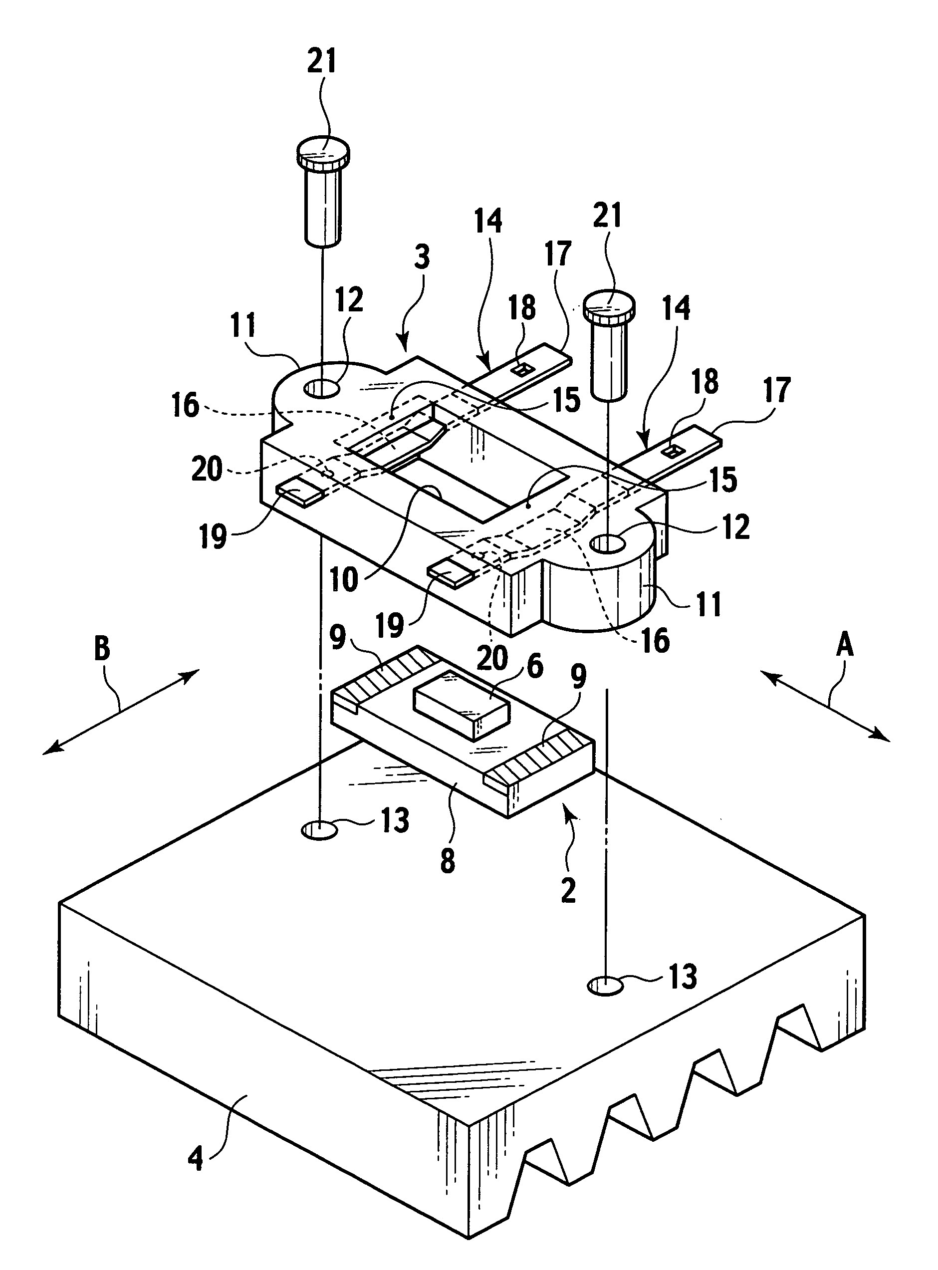
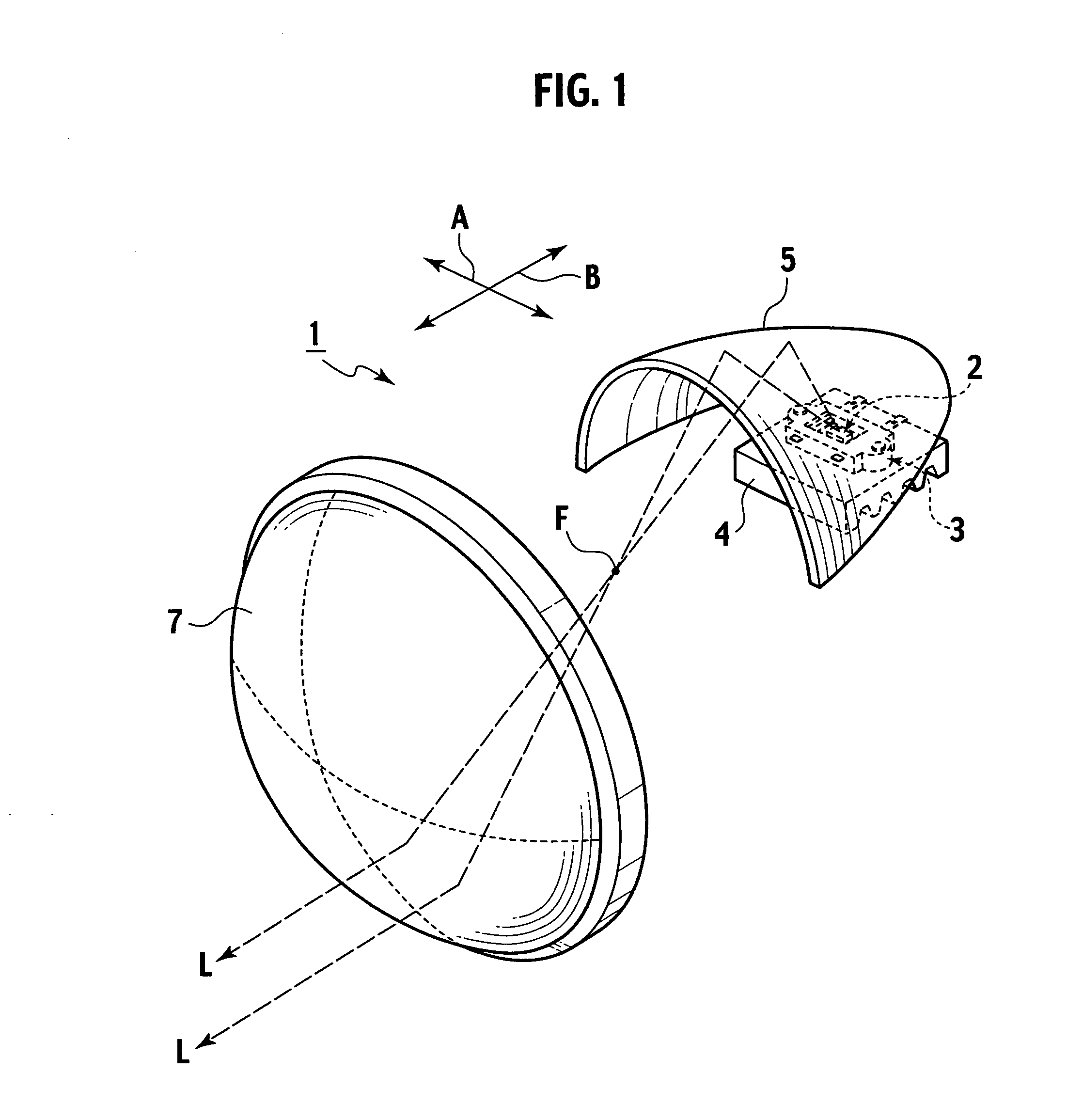
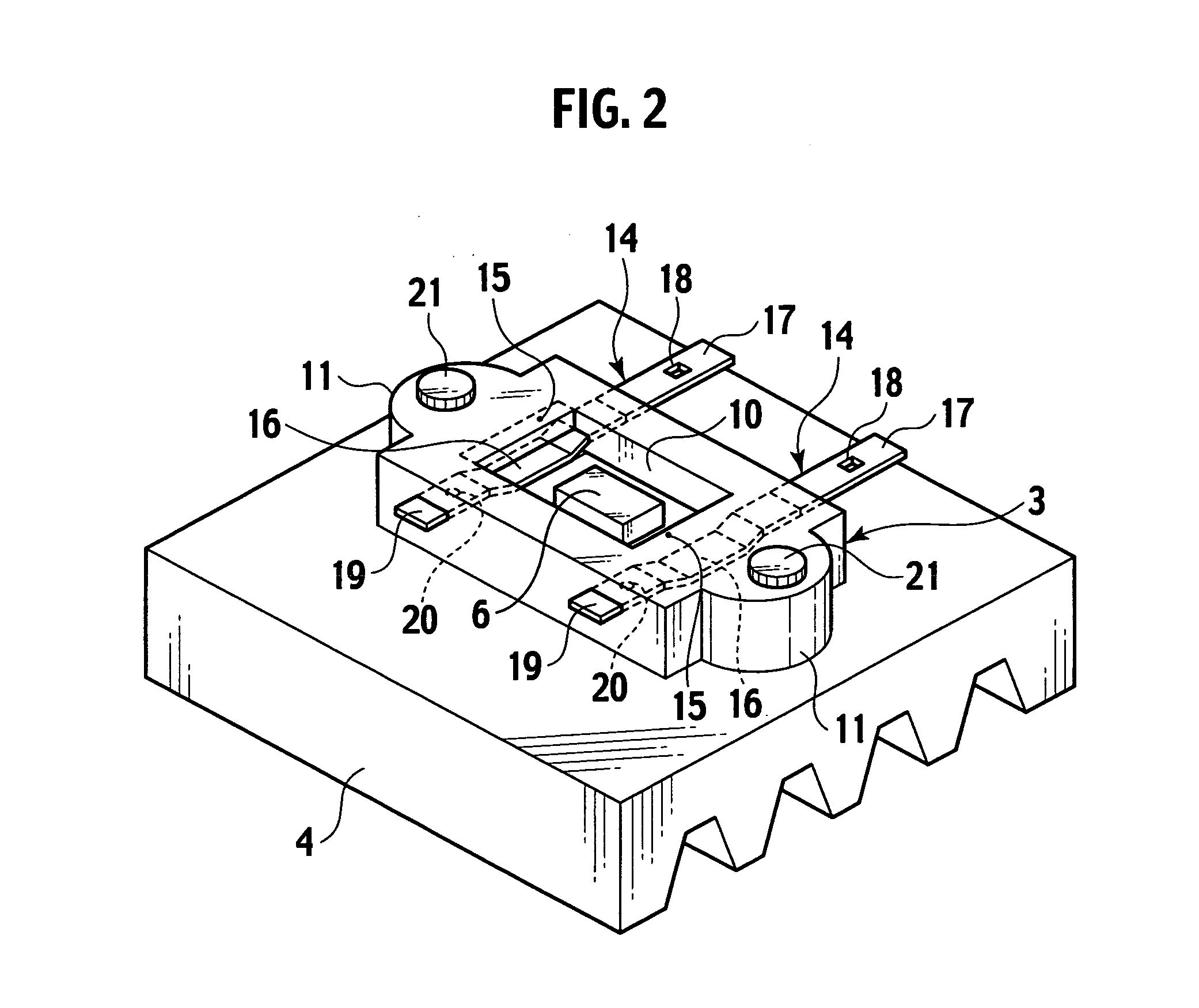
[0016]FIG. 1 is a perspective view showing an internal structure of a head lamp to which a fixing structure for a light emitting diode according to an embodiment of the present invention is applied, FIG. 2 is a perspective view showing the fixing structure for a light emitting diode, FIG. 3 is a exploded perspective view showing the fixing structure for a light emitting diode, FIG. 4 is a plan view showing a holder housing a light emitting diode in an opening thereof, FIG. 5 is a bottom view of the holder and the light emitting diode, FIG. 6 is a cross-section taken along a line VI-VI shown in FIG. 4, FIG. 7 is a cross-section showing a state in which the light emitting diode is removed from the holder, and FIG. 8 is a cross-section taken along a line VIII-VIII shown in FIG. 4.

[0017]Head lamps that are positioned on both sides in a front part of a vehicle are cons...


PUM


Abstract

A holder in which a light emitting diode is set in an opening is fixed on a heat sink so that power feeding units of the light emitting diode are pushed toward the heat sink by metal wiring bodies. Therefore, the light emitting diode and the heat sink can be brought into close contact with each other and heat dissipation performance of the heat sink can be improved.

Description

CROSS REFERENCE TO RELATED APPLICATIONS[0001]This application is based upon and claims the benefit of priority from prior Japanese Patent Application P2006-340337 filed on Dec. 18, 2006; the entire contents of which are incorporated by reference herein.BACKGROUND OF THE INVENTION[0002]The present invention relates to a fixing structure for a light emitting diode, and, more particularly to a fixing structure for a light emitting diode that is suitable for a vehicle lamp device.[0003]Conventionally, as a fixing structure for a light emitting diode, as disclosed in Japanese Patent Application Laid-Open No. 2006-66108, there is known a structure that a light emitting diode having a power feeding unit on a surface of a substrate is held being sandwiched between an attachment in which a wiring unit to supply power to the light emitting diode is embedded and a bottom-surface supporting member, and the light emitting diode held with the attachment and the bottom-surface supporting member is...

Claims


Application Information

Patent Timeline
Patent Type & Authority Applications(United States)
IPC IPC(8): F21V29/00
CPCF21S48/115F21V19/0025F21Y2101/02F21V19/007F21V19/0055F21Y2115/10F21S41/141F21S41/147F21S41/192
Inventor TOKUNAGA, HIROTO
Owner ICHIKOH IND LTD
Why Eureka
Try Eureka