
Lightning Arrester System for a Wind Generator Blade

a technology of arrester system and wind generator, which is applied in the installation of lighting conductors, machines/engines, mechanical equipment, etc., can solve the problems of high potential created between the two, no general knowledge of any technique for which efficacy has been demonstrated, and limited experience in relation to the method used for protection against lightning

Active Publication Date: 2008-06-19
GAMESA INNOVATION & TECH SA
View PDF6 Cites 32 Cited by
  • Summary
  • Abstract
  • Description
  • Claims
  • Application Information

AI Technical Summary

Benefits of technology

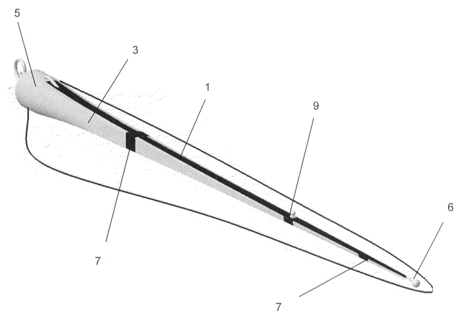
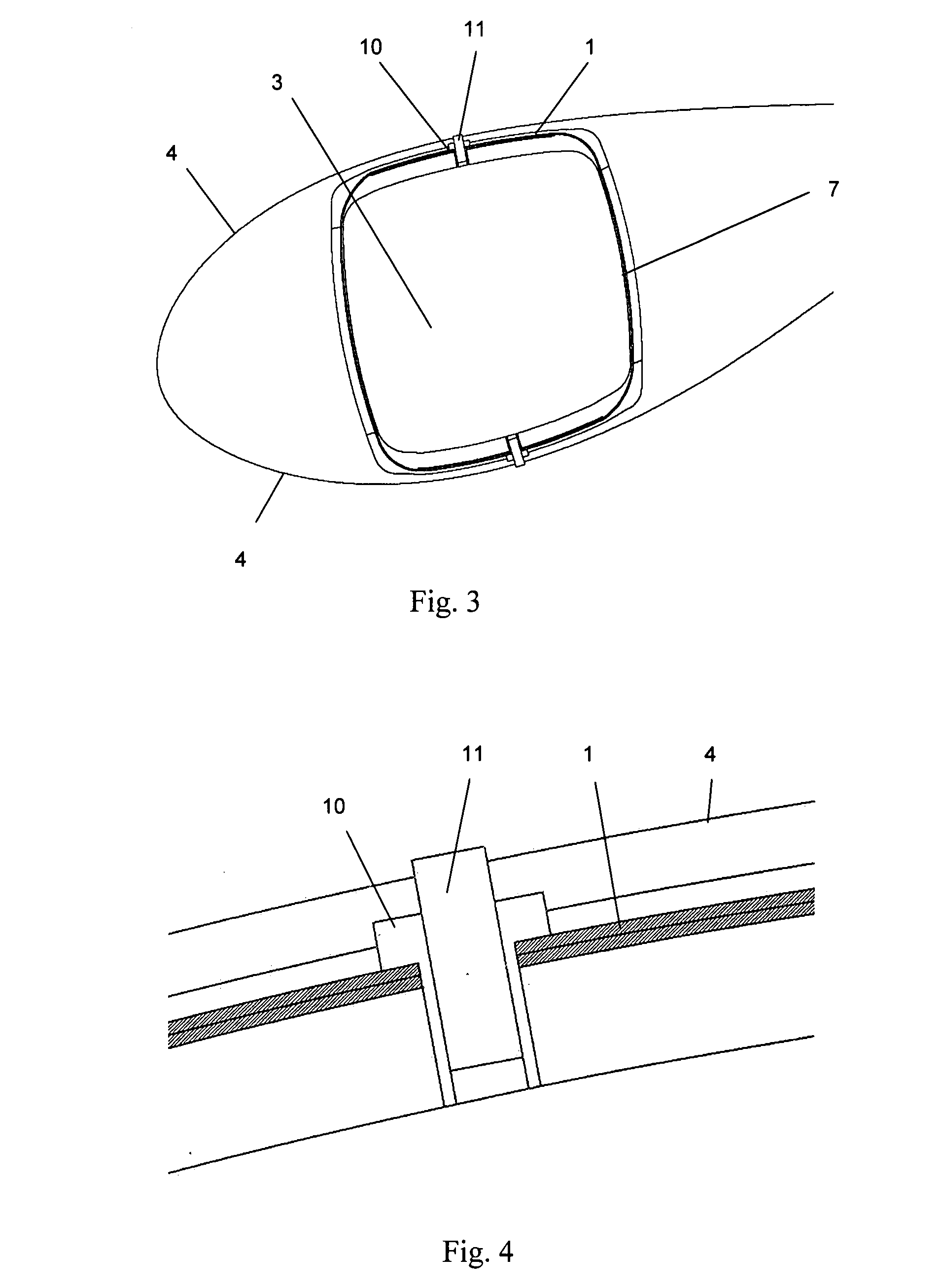
The invention is a lightning arresters system for blades that uses copper strips integrated into the blade to prevent lightning strike. The copper strips act as the main conductor of the system and are connected to intermediate receivers on the blade. The design of the receivers prevents direct impact of lightning with the carbon fibre laminates, minimizing damage to the blade. The system is efficient in conducting lightning current and protects the carbon fibre laminates from current impact.

Problems solved by technology

The inclusion of carbon fibre in the manufacturing of wind turbine blades is quite new and although its use is fairly extensive amongst the most important companies in the sector, the experience in relation to the method used for protection against lightning is still fairly limited and there is no general knowledge of any technique for which efficacy has been demonstrated.
The problem with leaving conductor elements insulated is the high difference in potential which is created between them due to induction phenomena caused by the lightning when it passes through the lightning arrester system.
This difference in potential may give rise to an arc-over, which could be fatal in the case which concerns us where the carbon fibre laminate constitutes the main resistant part of the blade.
There are different metal mesh based systems which attempt to prevent any intervention of the carbon fibre compound in the potential differences problem yet none of them have been shown to be efficient at resolving the problem.

Method used


Image

  • Lightning Arrester System for a Wind Generator Blade
  • Lightning Arrester System for a Wind Generator Blade
  • Lightning Arrester System for a Wind Generator Blade

Examples


Embodiment Construction

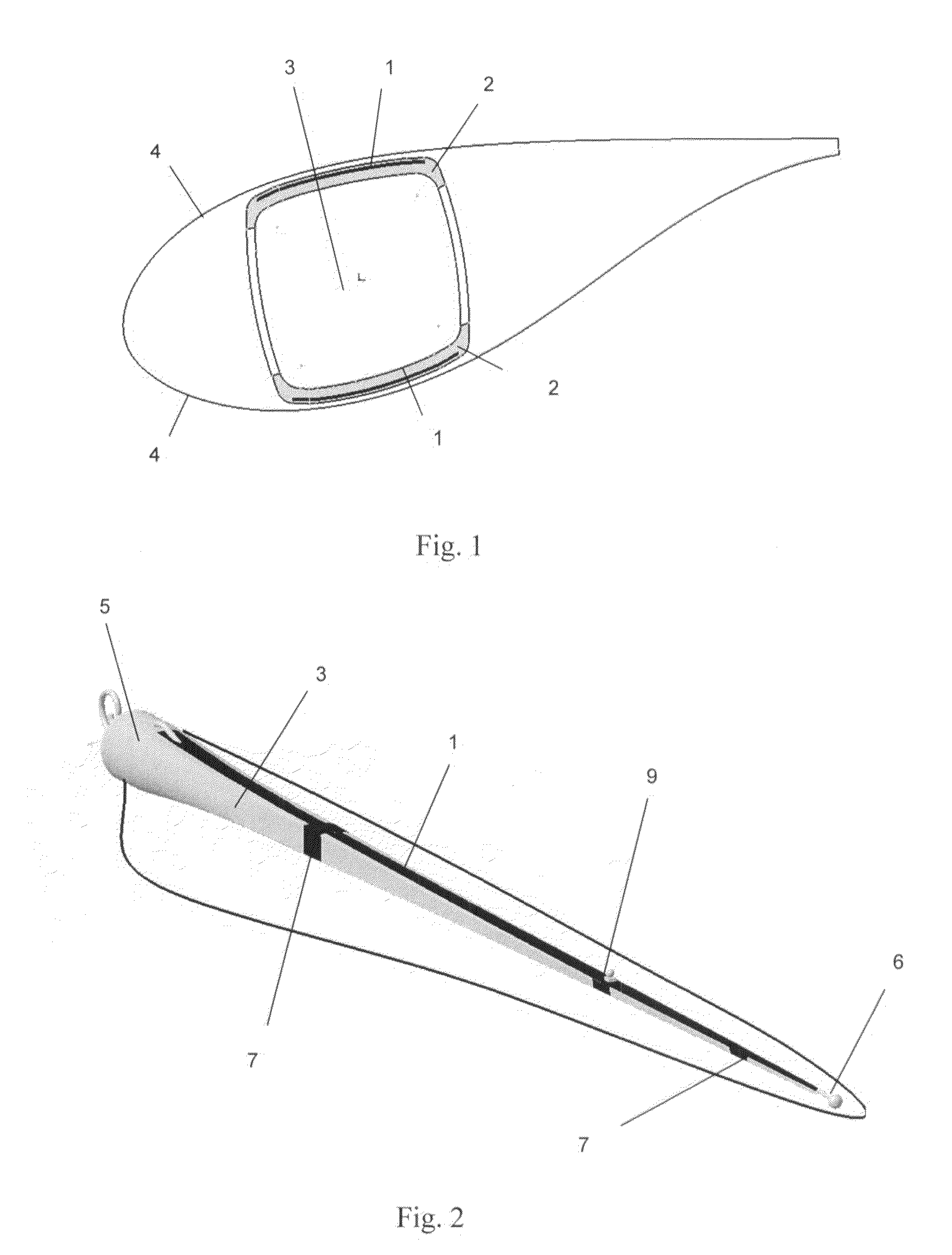
[0017]One particular embodiment may consist of two strips of copper (1), each situated in contact with one of the two main carbon fibre laminates (2) of the beam (3), said laminates are arranged on both sides of the beam (3), called airfoils, and are secured facing the blade shells (4).

[0018]As FIG. 1 shows, this system replaces the main copper cable currently used for two thin bands of copper (1) which run along the entire beam (3) in direct contact with the carbon fibre (2) so that both are equipotential, thus avoiding arc-over between said elements.

[0019]Due to the electrical characteristics of the carbon fibre laminates (2) and of the strips of copper (1), in the case of a lightning impact the majority of the current circulates through the copper strip (1) thus preventing any harm being caused to the laminates.

[0020]The copper strip (1) is located along the entire beam airfoil (3) and in direct contact with the beam's carbon fibre laminates (2) and is covered with the subsequent...


PUM


Abstract

The invention relates to a lightning arrester system for wind generator blade, which replaces the standard main copper cable and which employs two strips of copper that extend along the entire length of the beam such as to be in direct contact with the carbon fibre. In this way, the carbon fibre laminate and the copper strip are always at the same potential, thereby preventing any possible arc-over between the two elements. The carbon fibre laminate is barely affected by the passage of current owing both to the electrical characteristics of the two components and to the selected configuration which conveys most of the current through the copper strips. In addition, with said novel system it is possible to position intermediate receivers on the actual laminates and in direct contact with the copper strip.

Description

SUBJECT OF THE PATENT[0001]The subject of the patent is a lightning arrester system for transmission and reception of lightning in wind turbine blades. An important characteristic is that a part of this blade has carbon fibre laminates which have strips of copper embedded between them and which extend along the entire blade.BACKGROUND OF THE INVENTION [0002]The inclusion of carbon fibre in the manufacturing of wind turbine blades is quite new and although its use is fairly extensive amongst the most important companies in the sector, the experience in relation to the method used for protection against lightning is still fairly limited and there is no general knowledge of any technique for which efficacy has been demonstrated.[0003]Both the regulations applicable to wind turbines and existing literature on the subject, speak of the an efficient method of protecting fibre glass blades against lightning consisting of a lightning arrester system based on occasional receivers located alo...

Claims


Application Information

Patent Timeline
Patent Type & Authority Applications(United States)
IPC IPC(8): F01D5/14
CPCF03D1/065F03D11/0033F05B2240/30Y02E10/722F05C2253/04H02G13/00Y02E10/721F05B2280/6003F03D80/30Y02E10/72F03D80/00
Inventor LLORENTE GONZALEZ, JOSE IGNACIOVELEZ ORIA, SERGIO
Owner GAMESA INNOVATION & TECH SA
Learn More