
Method and Apparatus for Pressure Infusion and Temperature Control of Infused Liquids

a technology of temperature control apparatus and infused liquid, which is applied in the direction of process and machine control, instruments, other medical devices, etc., can solve the problems of insufficient gravity force to drive certain viscous liquids, insufficient expansion of the bladder to apply adequate pressure to the liquid-filled bag, and inability to operate efficiently. to achieve accurate temperature measurement

Inactive Publication Date: 2008-06-19
MEDICAL SOLUTIONS INC
View PDF98 Cites 81 Cited by
  • Summary
  • Abstract
  • Description
  • Claims
  • Application Information

AI Technical Summary

Benefits of technology

"The present invention is a method and apparatus for pressure infusion and temperature control of infused liquids. It involves using a liquid-filled bag and an inflatable pressure device to control the pressure and temperature of the liquid during infusion. The invention allows for individual control of heating and flow rate of the infused liquid, as well as control of temperature based on the flow rate and the patient's needs. The invention also includes a heating assembly disposed along an intravenous tube to maintain the liquid at a desired temperature. The technical effects of the invention include improved control over the temperature and flow rate of infused liquids, which can help to prevent complications and ensure patient safety."

Problems solved by technology

However, gravitational forces may be insufficient to drive certain viscous liquids, such as refrigerated blood, into the patient, or drive liquids into the patient at a sufficient rate.
In particular, the Hinck et al device includes a bladder that substantially surrounds a liquid-filled bag, however, the bladder may not expand sufficiently to apply adequate pressure to the liquid-filled bag when small volumes of liquid are present within the liquid-filled bag, thereby operating less efficiently when smaller volumes of liquid reside within the liquid-filled bag and requiring premature replacement of the liquid-filled bag prior to utilization of liquid within that bag.
Similarly, the Mandl infuser utilizes a strap to maintain a bladder about a liquid-filled bag wherein pressure exerted by the bladder on the liquid-filled bag is focused substantially coincident the strap, thereby operating less efficiently, especially when smaller volumes of liquid reside within the liquid-filled bag, since various pressures are applied to different portions of the liquid-filled bag (e.g., the bladder portions disposed near the strap apply the greatest amounts of pressure, while the bladder portions disposed furthest from the strap apply the least amounts of pressure), and requiring premature replacement of the liquid-filled bag prior to utilization of liquid within that bag.
In other words, when the liquid-filled bags become partially depleted and thin, the bladders of the Hinck et al and Mandl devices may not maintain adequate pressure on the thinner bags for infusion of liquid into a patient.
Further, the bladders of these devices generally include certain dimensions, thereby only being compatible or satisfactorily operable with liquid-filled bags of a particular size.
Moreover, the Hinck et al and Mandl devices do not thermally treat the liquid-filled bags in any manner during infusion.
Further, infusion into a patient of liquids having temperatures below the normal body temperature may produce further complications, such as shock, cardiac dysfunction, increased coagulation time, and in certain patients, clumping of blood cells.
In particular, the prior art warmer systems heating liquid within an intravenous or other tube tend to employ and control a single heating element disposed along the tube, thereby limiting control accuracy of the liquid temperature and typically producing hot spots (e.g., certain sections of the tube may become warmer than other sections of the tube) along the tube.
Some of the prior art warmer systems require pre-heating of a liquid-filled bag prior to use in and external of those systems, thereby requiring additional time to heat the liquid.
Further, the prior art warmer systems heating liquid within an intravenous or other tube typically rely on gravitational forces to direct the liquid to the patient.
These gravitational forces may be inadequate to produce desired flow rates or enable flow of viscous solutions as described above.
In addition, the prior art warmer systems typically control liquid heating based solely on temperature measurements of the liquid, thereby limiting control options and providing for less accurate control.
The prior art warmer systems typically maintain activation of heating elements in cases of excessive liquid or heating element temperatures or interruptions in liquid flow, thereby enabling the heating elements to heat the liquid to temperatures beyond the liquid utilization temperature range and possibly injure a patient and / or damage an intravenous or other tube.
A further disadvantage of the prior art warmer systems heating liquid within an intravenous or other tube is that the temperature of liquid contained within a liquid-filled bag or receptacle is typically substantially below a desired temperature, thereby requiring significant heating of the liquid during infusion as the liquid traverses the tube.

Method used


Image

  • Method and Apparatus for Pressure Infusion and Temperature Control of Infused Liquids
  • Method and Apparatus for Pressure Infusion and Temperature Control of Infused Liquids
  • Method and Apparatus for Pressure Infusion and Temperature Control of Infused Liquids

Examples


Embodiment Construction

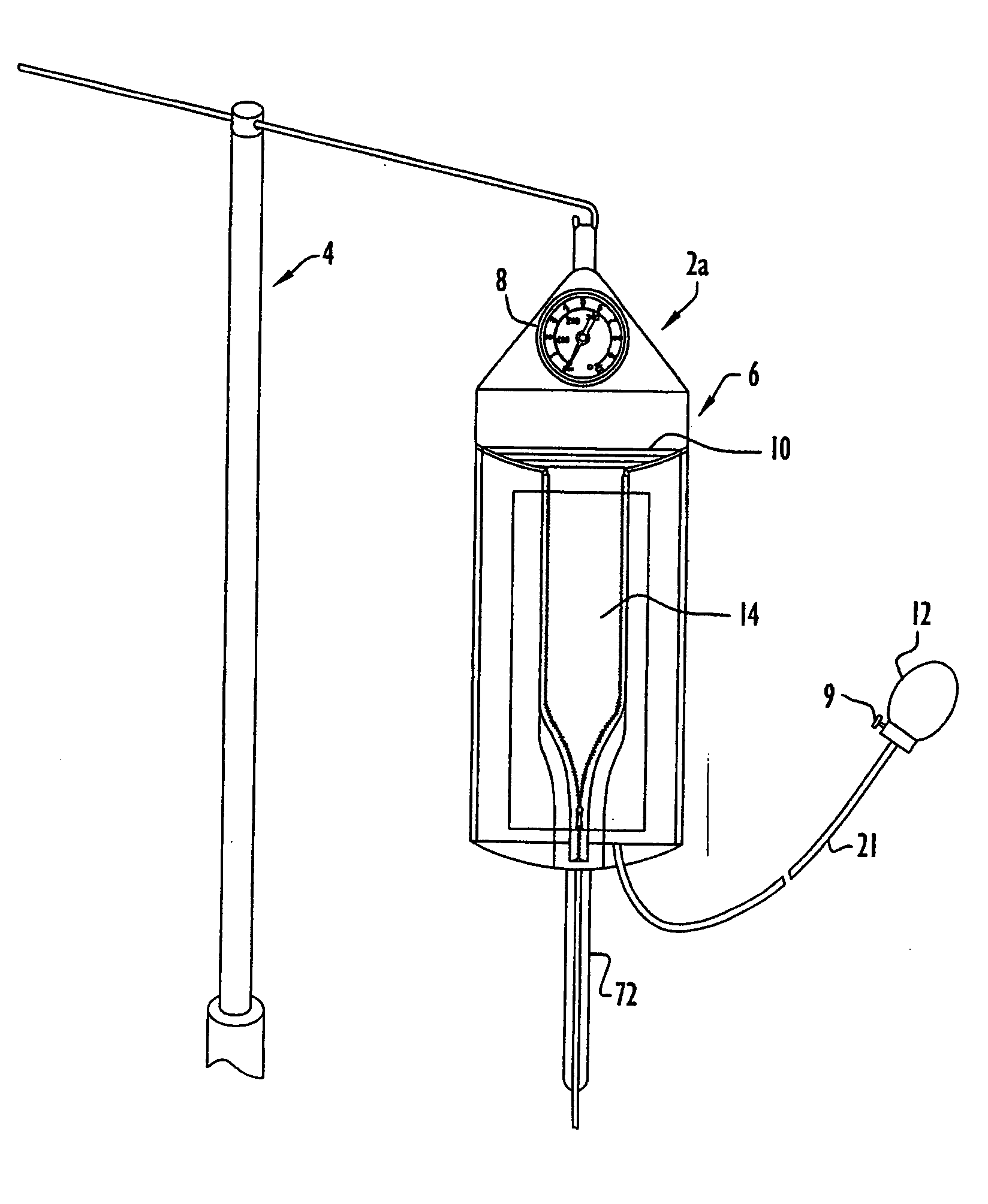
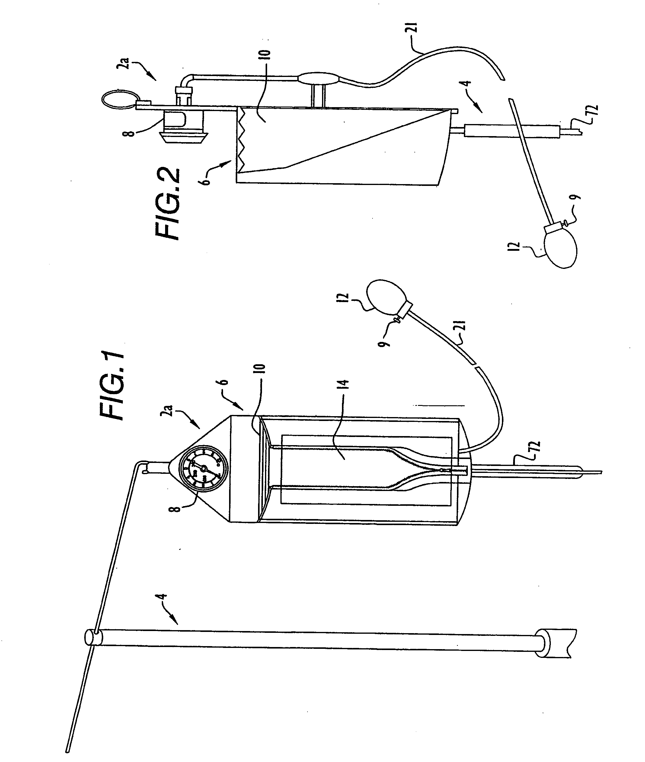
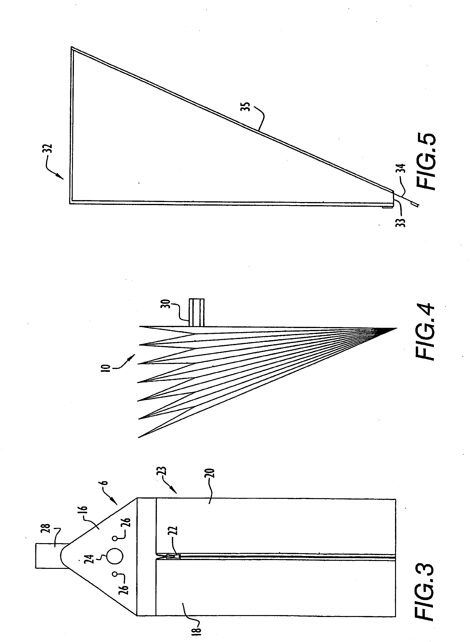
[0049]A pressurized infusion apparatus or system for irrigating a patient or directing infused liquids into a patient is illustrated in FIGS. 1-2. Specifically, system 2a is typically mounted on a conventional intravenous (I.V.) pole 4 and includes a receptacle 6 for containing intravenous solution or other liquid and engaging pole 4, a pressure gauge 8, an inflatable pressure device or bellows 10, a bulb 12 for regulating fluid pressure within the bellows via a hose 21, and an intravenous or other tube 72 for directing liquid from the receptacle to a patient. Receptacle 6 typically receives a liquid-filled bag 14 (e.g., a bag containing intravenous solution or other liquid) and bellows 10 wherein the bellows is disposed within a bellows bag 32 (FIG. 5) and positioned adjacent the liquid-filled bag. Hose 21 extends between bellows 10 and bulb 12 wherein manipulation of the bulb drives fluid into or from the bellows through hose 21. Hose 21 is typically implemented by a conventional ...


PUM


Abstract

A method and apparatus for pressure infusion and temperature control of infused liquids includes a receptacle for receiving a liquid-filled bag containing intravenous solution or other liquid and an inflatable pressure device. The inflatable pressure device is disposed within a pressure device bag and is positioned proximate the liquid-filled bag in the receptacle. The inflatable pressure device expands within the pressure device bag upon inflation and exerts pressure on the liquid-filled bag. A heating element may be disposed on the inflatable pressure device bag to heat the liquid-filled bag to a desired temperature. The liquid may alternatively be maintained at a desired temperature, while flowing to a patient via a heating assembly disposed along a tube. The heating assembly includes a sleeve having a slot for receiving the tube and a plurality of individually controlled heaters. An infrared sensing device is mounted proximate a drip chamber to ascertain a drip count, while a temperature sensor is disposed within a holder that is positioned toward the entry site on a patient. A heat controller controls the heaters based on a drip count, while a safety controller disables heater operation in response to liquid temperature exceeding the desired temperature. Thus, the safety controller and heat controller, in combination, control the heating assembly heaters based on liquid temperature and flow rate, respectively. Alternatively, the liquid-filled bag may be heated to a desired temperature whereby the heating assembly includes a single heater controlled by a controller to maintain the liquid at the desired temperature during infusion of the liquid into a patient.

Description

CROSS REFERENCE TO RELATED APPLICATIONS[0001]This application claims priority from U.S. Provisional Patent Application Ser. No. 60 / 040,885, filed Mar. 3, 1997, entitled “Method and Apparatus for Measurement and Control of Temperature for Infused Liquids”, and U.S. Provisional Patent Application Ser. No. 60 / 062,315, filed Oct. 17, 1997, entitled “Method and Apparatus for Pressure Infusion and Temperature Control of Infused Liquids”. The disclosures of the foregoing provisional patent applications are incorporated herein by reference in their entireties.BACKGROUND OF THE INVENTION[0002]1. Technical Field[0003]The present invention pertains to pressurized infusion and temperature control apparatus or systems for infused liquids. In particular, the present invention is directed toward pressurized infusion of liquids into a patient and / or temperature control of that liquid during infusion into a patient.[0004]2. Discussion of Prior Art[0005]Generally, intravenous (I.V.) solution or other...

Claims


Application Information

Patent Timeline
Patent Type & Authority Applications(United States)
IPC IPC(8): A61M5/172A61M5/148A61M5/168A61M5/44
CPCA61M5/1689A61M5/172A61M5/1424A61M2205/3653A61M5/445A61M5/148A61M2209/04A61M5/44A61M5/1483A61M2205/3368
Inventor FARIES, DURWARD I.HEYMANN, BRUCEBLANKENSHIP, CALVINDUBOSE, GEORGE T.
Owner MEDICAL SOLUTIONS INC
Learn More