Braided Electrical Lead

a technology of electrical leads and wires, applied in the field of medical electrical leads, can solve the problems of small cross section, inability to push, and is typically very floppy and not pushable, and achieve the effect of reducing the risk of injury, reducing the life of the flexor, and reducing the flexor

Active Publication Date: 2008-06-19
CIRTEC MEDICAL CORP
View PDF18 Cites 70 Cited by
  • Summary
  • Abstract
  • Description
  • Claims
  • Application Information

AI Technical Summary

Problems solved by technology

The lead, commonly formed of a polymeric material and being very small in cross section, is typically very floppy and not pushable.
Issues arise that relate to the orientation and spacing of the conductors as they tend to float inside the lead body tubing.
As the conductors float and potentially cross each other, flex life can be negatively impacted.
Using straight conductors is not optimal, as they break.
Also, it is hard to make a coil out of a cable, as there is need to put a great deal of stress on the cable as it is wound around a mandrel in order to make the coil stay after the mandrel is removed.

Method used


Image

  • Braided Electrical Lead
  • Braided Electrical Lead
  • Braided Electrical Lead

Examples


Embodiment Construction

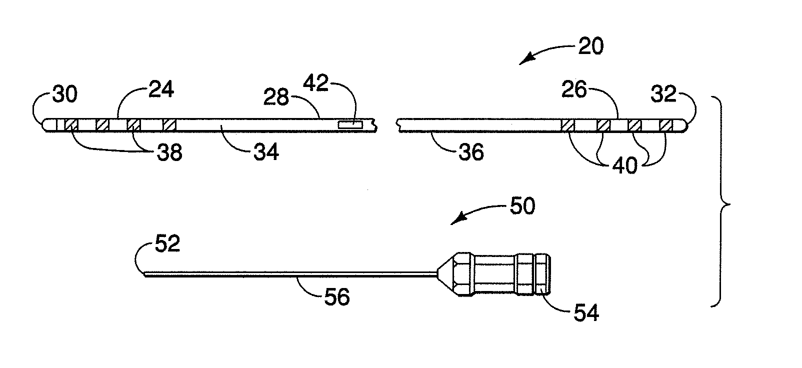
[0026]FIG. 1 illustrates a neurological stimulation lead 20, similar is some aspects, to the lead illustrated in U.S. Patent Application Pub. No. 2005 / 0021119, herein incorporated by reference. Lead 20 can incorporate a multi-conductor cable according to the present invention. Lead 20 has a distal region 24, a proximal region 26, and an intermediate region 28 disposed between the distal and proximal regions. In a preferred embodiment, the intermediate region is between the innermost distal and proximal electrical contacts described below. A stylet entrance or insertion port 42 is provided in the intermediate region 28. In other embodiments, the stylet entrance may be absent or lie in the proximal end. Lead 20 can be formed of a body or shaft 34 extending between a distal end 30 and a proximal end 32. Lead body 34 has an exterior surface or tubular side wall 36 and is preferably formed of a polymeric material, for example, polyurethane or silicone.

[0027]Lead distal region 24 may incl...


PUM


Abstract

An implantable electrical lead having a plurality of insulated conductor strands and a plurality of non-conductor strands braided together to maintain the spacing of the conductors from each other to prevent the crossing of the insulated conductor strands. The non-conductor strands are often polymeric strands. In some leads, the conductor strands and non-conductor strands are braided in opposite clockwise directions from each other. The conductor strands may travel adjacent each other in a clockwise direction, crossing non-conductors alternately over then under, with the immediately adjacent conductor strand doing the same but being out of phase. A diamond braid pattern is used in some embodiments. Braids may be formed over a removable mandrel, or a non-removable shaft or tube. Braiding can provide a structure which maintains its configuration after removal from a mandrel without requiring undue stress application to the strands.

Description

CROSS-REFERENCE TO RELATED APPLICATION[0001]The present application claims priority from U.S. Provisional Patent Application Ser. No. 60 / 870,782, filed Dec. 19, 2006.BACKGROUND OF THE INVENTION[0002]1. Field of the Invention[0003]The present invention is related generally to medical electrical leads. More specifically, the present invention is related to implantable electrical leads. The present invention may find use in implantable neurological devices, cardiac devices, as well as many other devices.[0004]2. Prior Art[0005]Implantable leads having externally exposed ring or band electrodes can be used to deliver electrical stimulation to surrounding tissue and / or to sense electrical energy produced by the surrounding tissue. Such leads are often implanted, for example, within the epidural or intrathecal spaces of the spinal column, along peripheral nerves, within the brain, and about the heart. Electrical stimulation of the spinal cord has been shown to be effective in relieving in...

Claims


Application Information

Patent Timeline
Patent Type & Authority Applications(United States)
IPC IPC(8): A61N1/05
CPCA61N1/0551A61N1/05
Inventor SWOYER, JOHN M.FARRELL, RICHARD M.FARRELL, BRIAN K.
Owner CIRTEC MEDICAL CORP
Why Eureka
Try Eureka