
Measuring arrangement for registering chemical and/or physical, measured variables, as well as measuring device therefor

a technology of measuring arrangement and measurement variable, applied in the direction of instruments, transmission systems, electric signal transmission systems, etc., can solve the problems of “available power” and the inability to fully utilize the potential of the measuring device, and the fluctuation of power over a wide range, so as to achieve low power and easy incorporation

Active Publication Date: 2008-06-19
ENDRESS HAUSER FLOWTEC AG
View PDF4 Cites 23 Cited by
  • Summary
  • Abstract
  • Description
  • Claims
  • Application Information

AI Technical Summary

Benefits of technology

The invention provides a measuring arrangement for measuring chemical and physical variables in flowable media and solid media. The arrangement includes a measuring device and a data processing system connected together through at least one pair of lines. The measuring device can generate multiple measured values and transmit them simultaneously to the data processing system. The arrangement is designed to be easily integrated into existing industrial data transmission systems and can incorporate existing fieldbus systems. The invention also provides a measuring device with a superordinated data processing system that can be used in existing industrial plants and data processing systems. The invention aims to improve the accuracy and safety of measuring arrangements and to facilitate their use in existing industrial settings.

Problems solved by technology

A special problem of such two-conductor field-devices is, however, that essentially only a single, physical, information carrier—here the electrical current, respectively its level, flowing in the line-pair—is provided for the measured values to be transmitted and that, as a result, instantaneously always only exactly a single measured value of the particular measuring device can be evaluated in the superordinated evaluating unit connected via the line-pair.
For the case, however, arising quite often, wherein the field device is a multivariable measuring device, for example a Coriolis mass flow / density meter, which is capable of ascertaining highly accurately and quasi in parallel, with high update rates, measured values of various kinds, for example the instantaneous and / or time-integrated mass flow, the instantaneous density and / or an instantaneous viscosity of the medium, the potential of this measuring device would not be able to be utilized in full measure, as a result being limited by the conventional, actually otherwise very advantageous, two-conductor technology.
A further problem of such measuring devices implemented in two-conductor technology is, additionally, that the electrical power actually usable by the measuring device electronics—for short, the “available power”—can fluctuate during operation over a wide range in practically unpredictable manner, as a result of changes of the measured variable as a function of time.
Making the situation more difficult is the fact that a large number of modern field devices of the described kind must, additionally, be so embodied electrically that they meet requirements for explosion safety.
Especially, such field devices are operated, in the case of required intrinsic explosion safety, with such a low electrical “available” power, that, in order not to bring about ignition conditions, sparks or arcs cannot be issued electrically, with also the electrical energy stored in all possible cases directly in the measuring device having to be taken into consideration in the total energy and power balance.
As a result of this, also the storage of momentarily excess electrical energy is only possible to a very limited, most often only insufficient, degree.
These three limit values are so chosen that, in the case of malfunction, for example in the case of short circuiting in the measuring device electronics, the maximally liberated amount of energy is not sufficient to produce an ignition-capable spark.

Method used


Image

  • Measuring arrangement for registering chemical and/or physical, measured variables, as well as measuring device therefor
  • Measuring arrangement for registering chemical and/or physical, measured variables, as well as measuring device therefor
  • Measuring arrangement for registering chemical and/or physical, measured variables, as well as measuring device therefor

Examples


Embodiment Construction

[0067]While the invention is susceptible to various modifications and alternative forms, exemplary embodiments thereof have been shown by way of example in the drawings and will herein be described in detail. It should be understood, however, that there is no intent to limit the invention to the particular forms disclosed, but on the contrary, the intention is to cover all modifications, equivalents, and alternatives falling within the spirit and scope of the invention as defined by the intended claims.

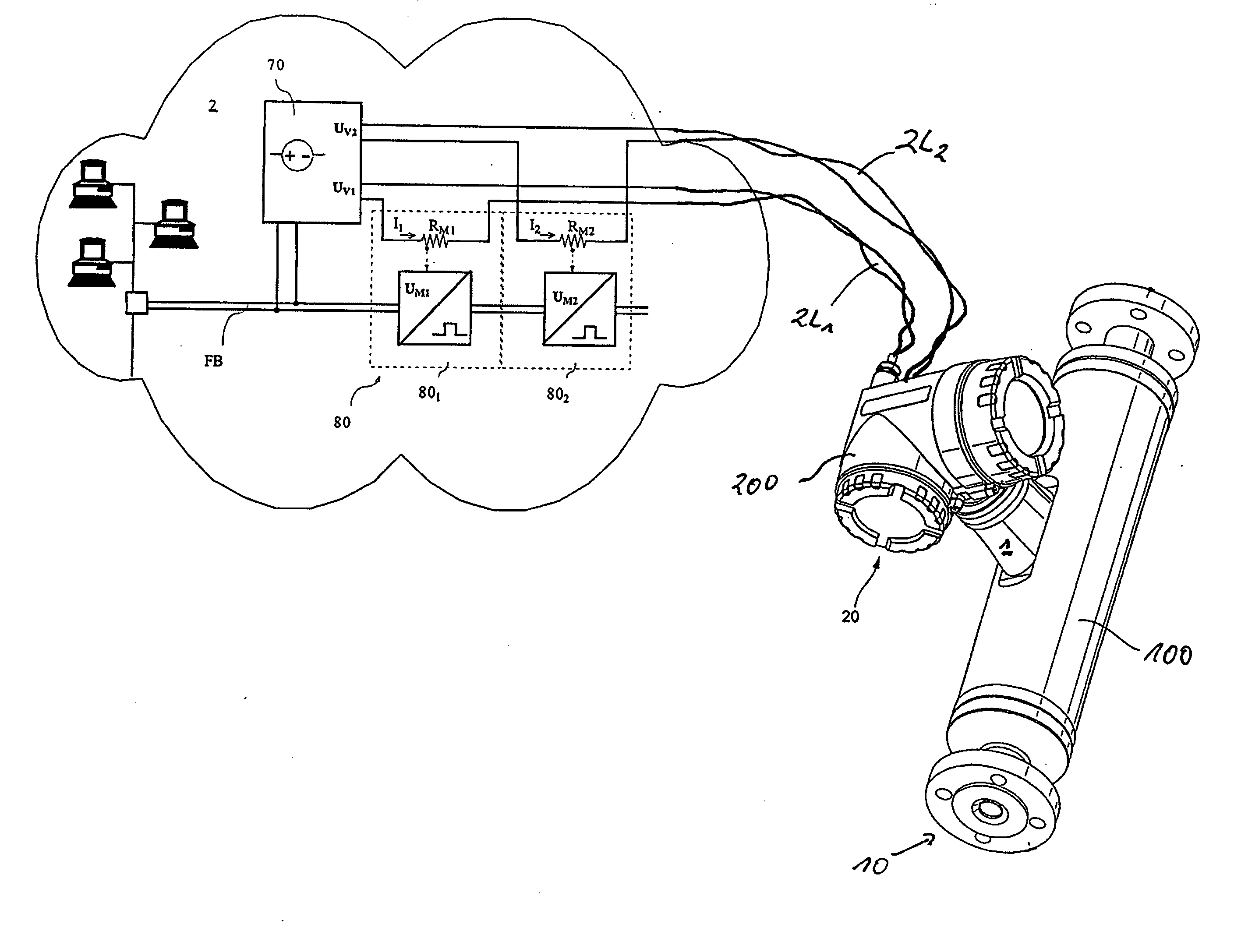
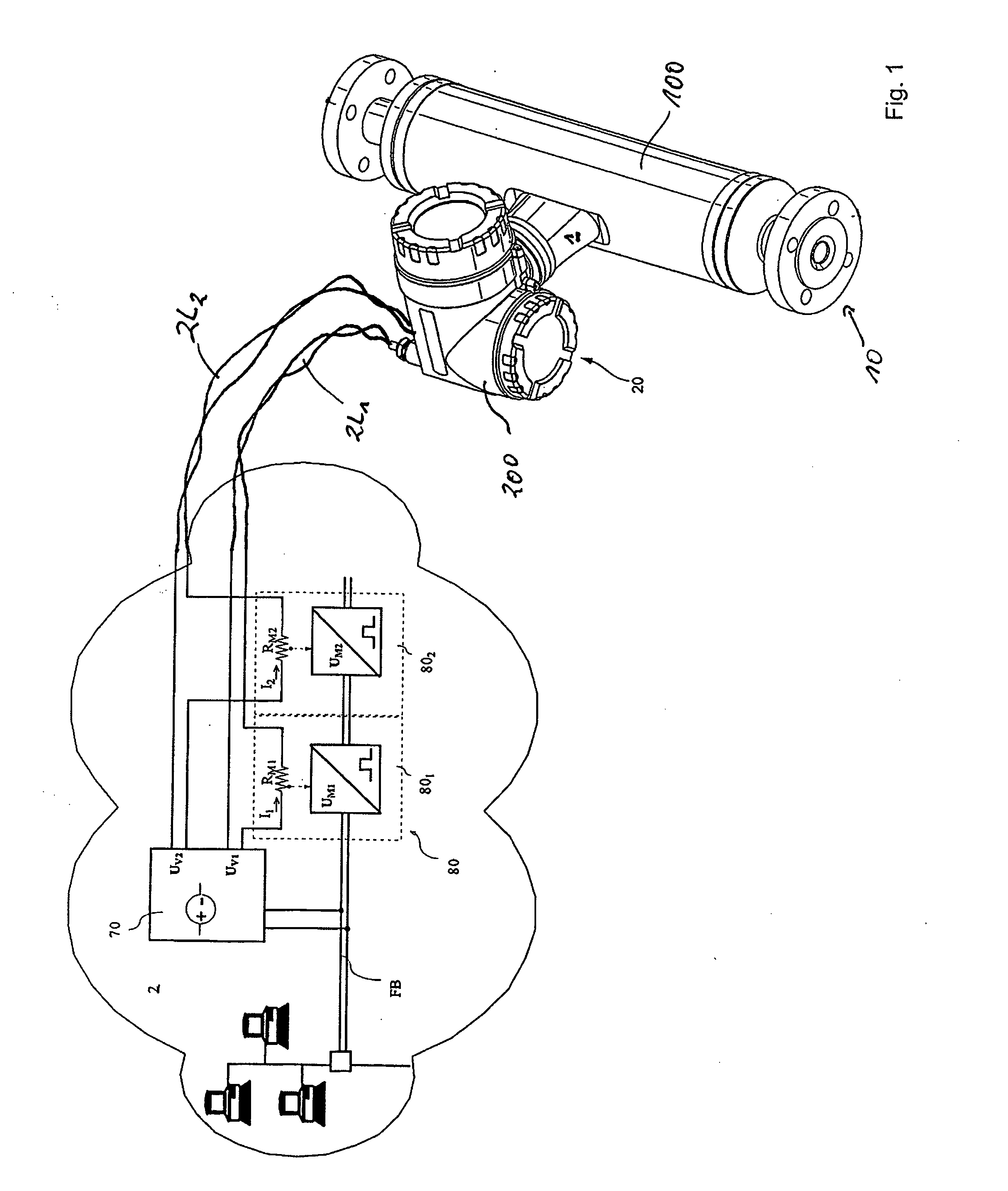
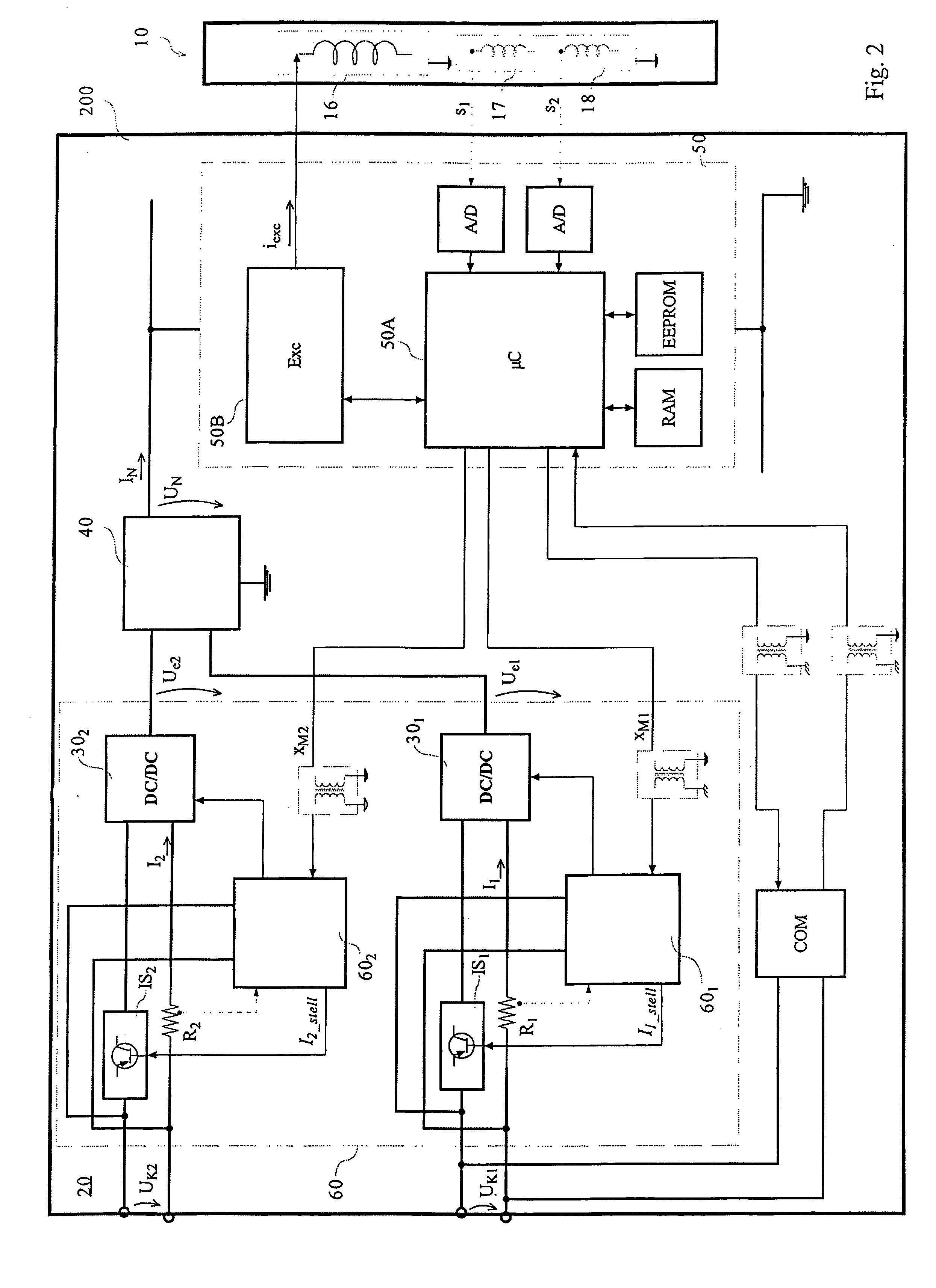
[0068]FIG. 1 shows an example of an embodiment of a measuring arrangement suited for use in industrial measurements and automation technology, in this case for registering chemical and / or physical, measured variables, especially of flowable, fluid media and / or flowable, solid, bulk media. The measuring arrangement includes for such purpose at least one measuring device 1, which repeatedly generates measured values representing the at least one measured variable to be registered, as we...


PUM


Abstract

A measuring arrangement of the invention includes: At least one measuring device, which generates, repeatedly during operation, measured values, especially digital, measured values, representing the at least one measured variable to be registered; as well as an electronic data processing system superordinated to the at least one measuring device, especially a data processing system which is spatially distributed and / or spatially remote from the measuring device. Measuring device and data processing system are connected together by means of at least two line-pairs, through each of which an electrical current flows, at least at times, during operation. According to the invention, the measuring device transmits the internally generated, measured values to the data processing system via both line-pairs. In this way, it is then possible to transmit a plurality of measured values simultaneously, when each of the two line-pairs is embodied as part of a two-conductor current-loop.

Description

CROSS-REFERENCES[0001]This application is a nonprovisional of U.S. Provisional Application 60 / 861,246 filed on Nov. 28, 2006 and U.S. Provisional Application 60 / 873,005 filed on Dec. 6, 2006 and which claims the benefit of German application numbers 102006056175.9 filed on Nov. 27, 2006.FIELD OF THE INVENTION[0002]The invention relates to a measuring arrangement for registering chemical and / or physical, measured variables, especially of flowable fluid media and / or flowable solid media, which measuring arrangement includes: At least one measuring device, which repeatedly generates during operation, by means of an internal measuring device electronics, measured values, especially digital, measured values, representing the at least one measured variable to be registered; as well as an electronic data processing system superordinated to the at least one measuring device, especially an electronic data processing system which is spatially distributed and / or spatially remote from the measu...

Claims


Application Information

Patent Timeline
Patent Type & Authority Applications(United States)
IPC IPC(8): G01R19/00G16Z99/00
CPCG01D9/005G06F19/00G08C19/02G16Z99/00
Inventor KARBULA, JIRILALLA, ROBERTENGSTLER, GERNOT
Owner ENDRESS HAUSER FLOWTEC AG
Learn More