Storage controller
- Summary
- Abstract
- Description
- Claims
- Application Information
AI Technical Summary
Benefits of technology
Problems solved by technology
Method used
Image
Examples
first embodiment
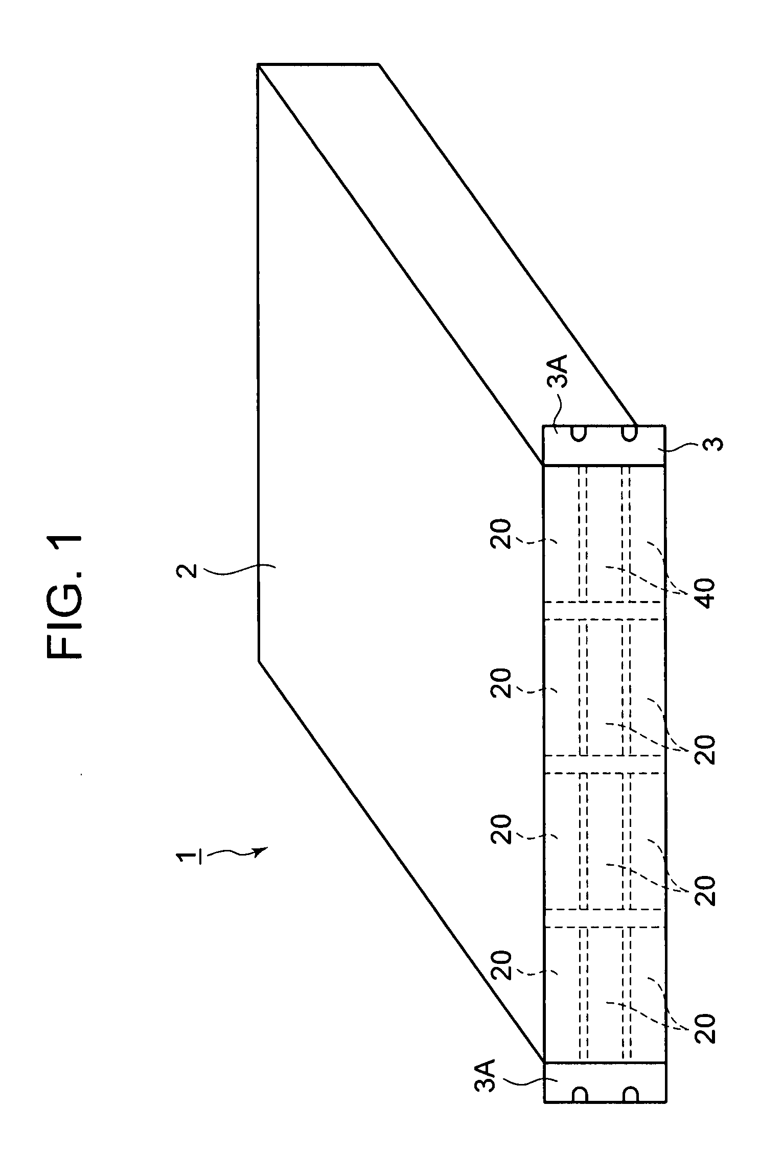
[0047]FIG. 1 is an oblique view showing the outside of a storage controller 1. This storage controller 1, for example, can be detachably connected to a rack.
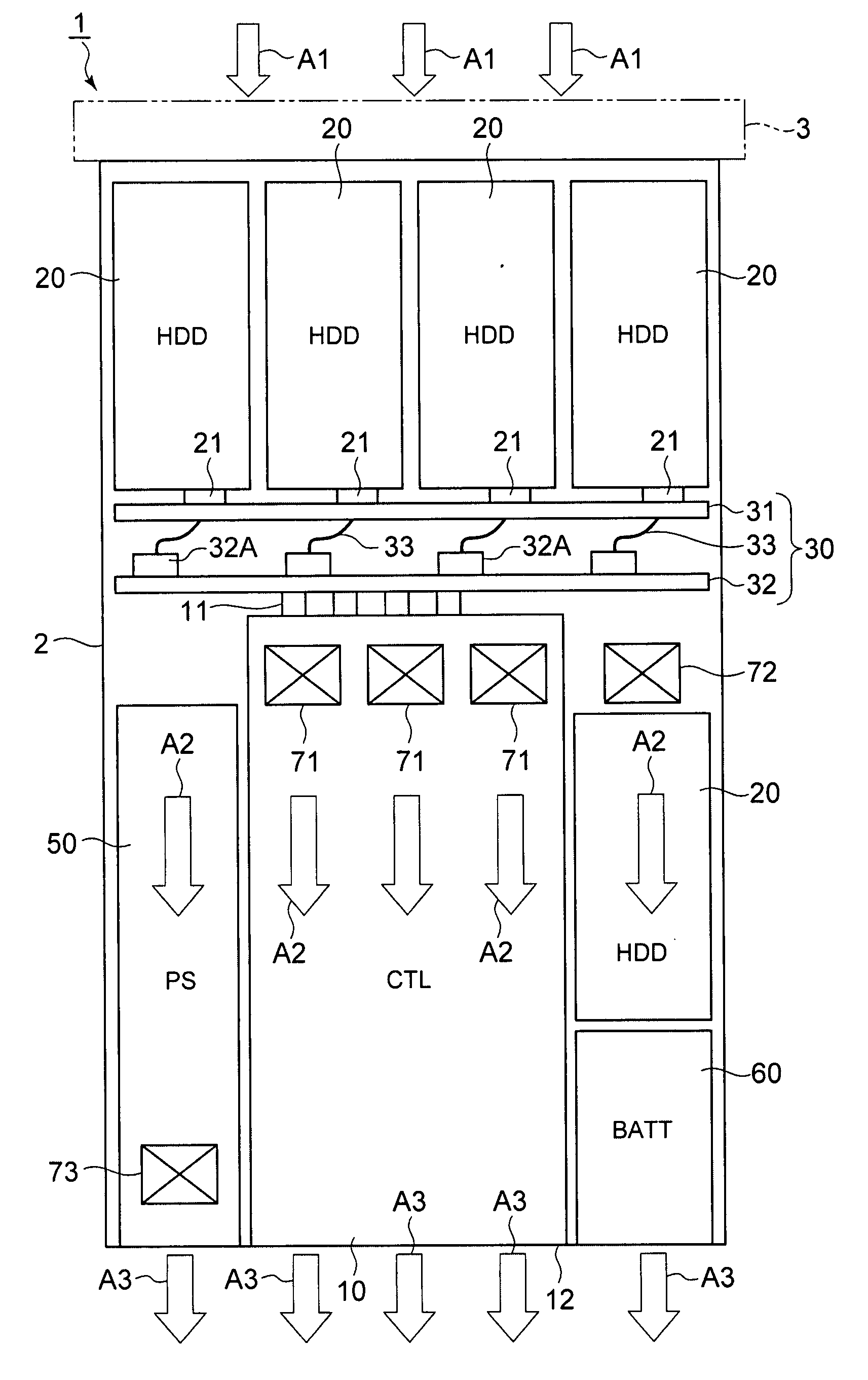
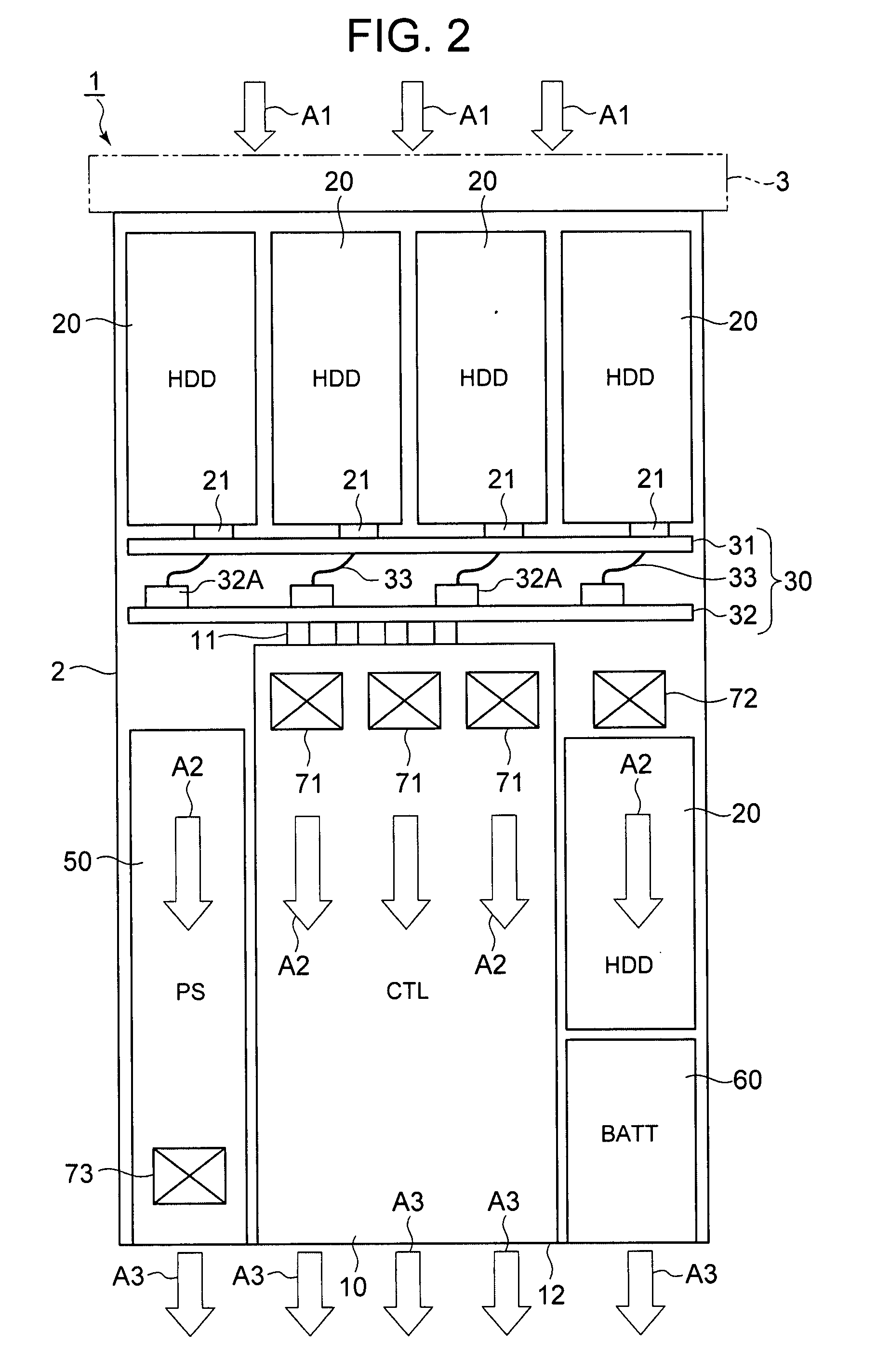
[0048]The storage controller 1, for example, comprises an enclosure 2, a front bezel 3, which is provided so as to cover the front side of the enclosure 2, and a plurality of disk drives 20 arranged in a matrix in the front side of the enclosure 2. Furthermore, as will be explained hereinbelow, a control board 10, a backboard 30, a repair drive slot 40 for adding a new disk drive when a disk drive 20 installed beforehand fails, a power device 50, a battery 60, and cooling fans 71, 72, 73 are respectively provided inside the enclosure 2.
[0049]A large number of openings are disposed in the front bezel 3. This is to allow air outside of the enclosure 2 to flow into the inside of the enclosure 2. Mounting parts 3A are disposed at both ends of the front bezel 3. The storage controller 1 can be detachably mounted to another enclosure,...
second embodiment
[0107]A second embodiment will be explained based on FIGS. 9 and 10. The following embodiments, including this embodiment, are equivalent to variations of the first embodiment explained hereinabove. Therefore, the following explanations will focus on those parts that differ from the first embodiment. In this embodiment, copying from a disk drive 20 in which a failure has occurred (also called a failed disk hereinafter) to a spare disk is attempted prior to commencing a correction copy.
[0108]FIG. 9 is a schematic diagram respectively showing the power capacity and power supply status of a power device 50 according to this embodiment. In the first embodiment, it was explained that the respective power devices 50 comprise only enough power capacity to be able to simultaneously supply direct current power to 10 disk drives 20. By contrast, the respective power devices 50 of this embodiment each comprise power capacity that enables direct current power to be simultaneously supplied to 11...
third embodiment
[0118]FIG. 11 is a plan view showing a storage controller 1 related to a third embodiment with the enclosure 2 and front bezel 3 removed. In this embodiment, a backboard 30A is used instead of the backboard 30 of the first embodiment.
[0119]This backboard 30A is constituted from a single board, and the respective disk drives 20 are connected to the front side thereof. The respective control boards 10 are connected to the rear side of the backboard 30A.
[0120]Being constituted like this, this embodiment also exhibits the same effect as the above-mentioned first embodiment. In addition to this, in this embodiment, since the backboard 30A is made of a single board, it is possible to reduce the number of component parts and the number of assembly processes compared to the first embodiment.
PUM
 Abstract
Description
Claims
Application Information
 - R&D
- Intellectual Property
- Life Sciences
- Materials
- Tech Scout
- Unparalleled Data Quality
- Higher Quality Content
- 60% Fewer Hallucinations
Browse by: Latest US Patents, China's latest patents, Technical Efficacy Thesaurus, Application Domain, Technology Topic, Popular Technical Reports.
© 2025 PatSnap. All rights reserved.Legal|Privacy policy|Modern Slavery Act Transparency Statement|Sitemap|About US| Contact US: help@patsnap.com


