Method and device for non-contact measurement of the alignment of motor vehicle wheels

a technology for motor vehicles and wheels, applied in measurement devices, instruments, using electrical means, etc., can solve the problems of large measurement error, inconvenient use, and inconvenient us

Active Publication Date: 2008-06-26
FASEP 2000
View PDF22 Cites 39 Cited by
  • Summary
  • Abstract
  • Description
  • Claims
  • Application Information

AI Technical Summary

Benefits of technology

[0034]For this purpose, according to an advantageous embodiment of the invention, the method provides for a preliminary step aimed at determining the position of said motor vehicle with respect to the reference planes on the basis of the position of the acquisition devices with respect to a single reference system. In substance, this entails identifying the position of all the centers of the video cameras or other image acquisition devices with respect to the center of a reference system, taken as absolute, centere...

Problems solved by technology

This procedure is not popular with users, also due to the intrinsic danger of moving a vehicle located on a vehicle lift.
The aforesaid systems have the following problems or disadvantages:the need to position the equipment by fixing it to the wheel (being measured); therefore, the measurement is intrusive;increase in measurement times caused by mounting;mounting precision: an error in the positioning of the target on the wheel causes a larger error in the measurement of the angles;mounting stability: the targets must be mounted on the wheel with extremely stable connections to prevent propagation of measurement errors during movements and rotations of the wheel in the normal operations to set the characteristic angles.
These systems are characterized by their considerable constructional complexity.
The disadvantage is that, as the measurement is based on calculation of t...

Method used


Image

  • Method and device for non-contact measurement of the alignment of motor vehicle wheels
  • Method and device for non-contact measurement of the alignment of motor vehicle wheels
  • Method and device for non-contact measurement of the alignment of motor vehicle wheels

Examples


Embodiment Construction

Description of the Components of the Measurement System

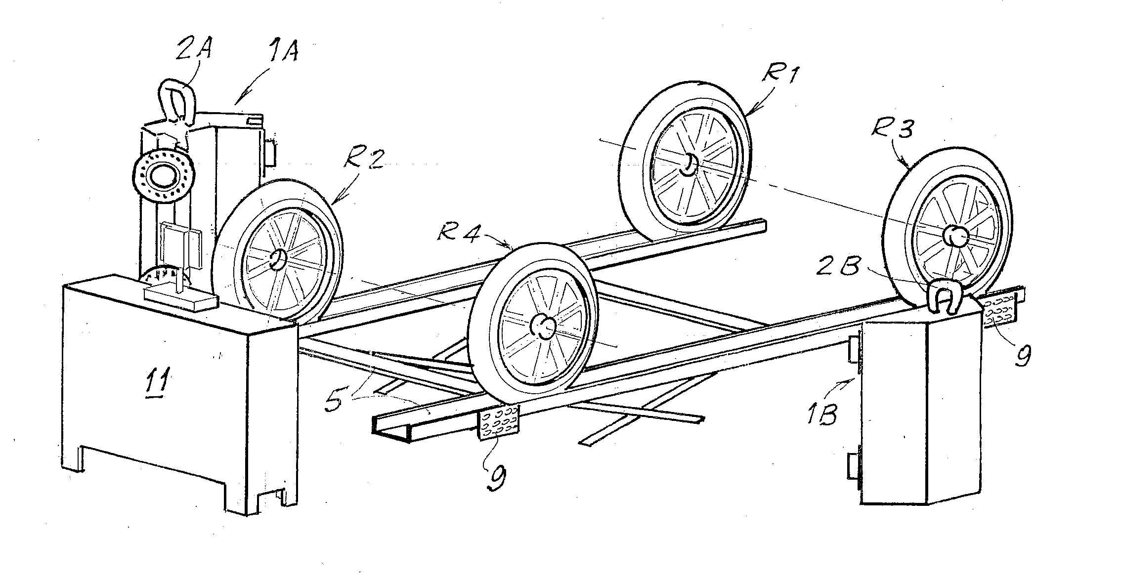
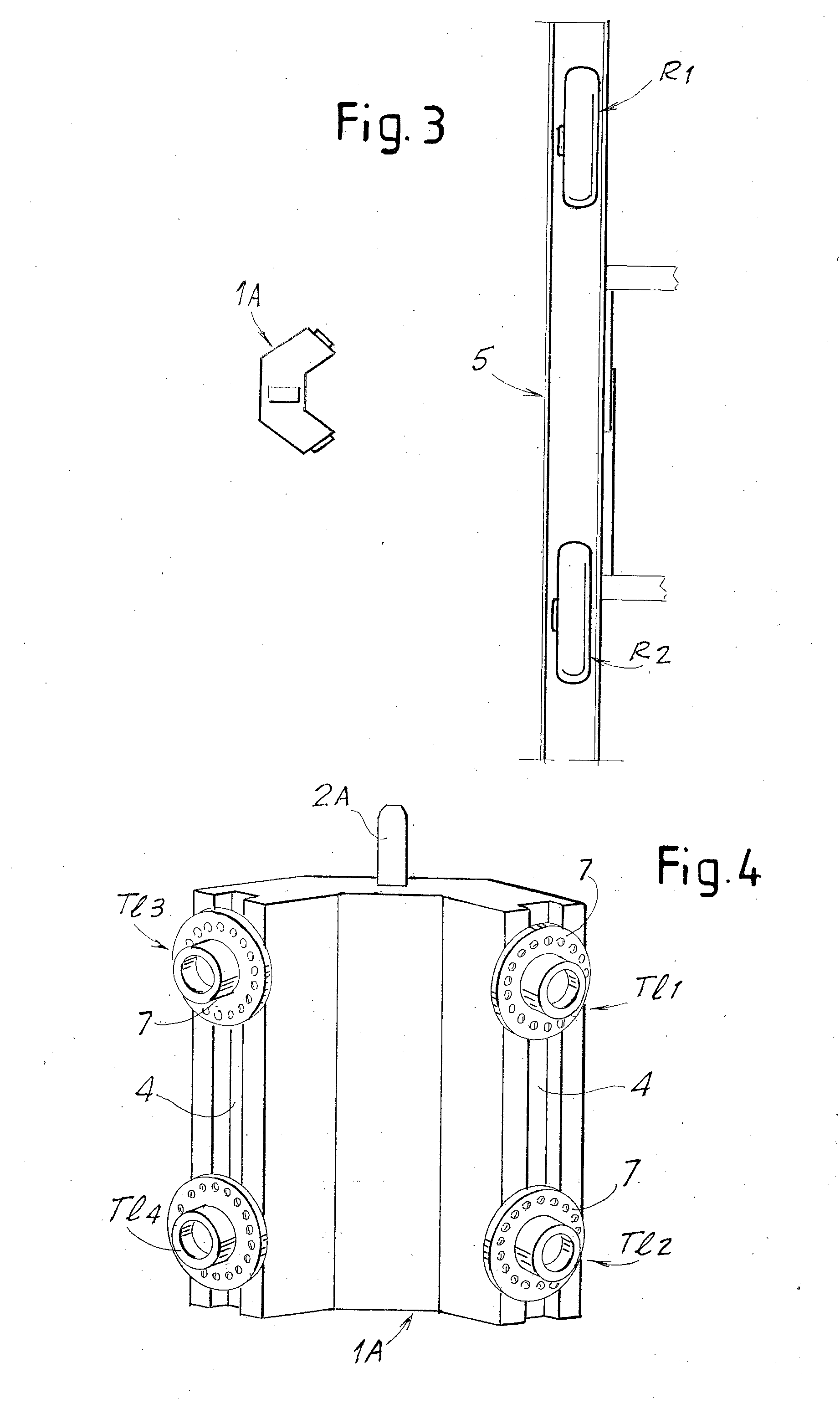
[0064]With reference to FIGS. 3 to 5, the components of the measurement device will initially be described, limited to what is necessary to understand the present invention. Subsequently, there will be described the operating principle and the method to determine the toe and camber angles using the device illustrated.

[0065]In an advantageous embodiment, the system comprises an acquisition column for each side of the vehicle. The columns are indicated with 1A and 1B in the diagram in FIGS. 3-5. Preferable, four video cameras, for example CCD or CMOS cameras, are mounted in each column 1A, 1B. In the diagram the video cameras are indicated with TI1, TI2, TI3, TI4 for the column 1A and TI5, TI6, TI7, TI8 for the column 1B. They can be movable, for example along guides 4 integrated in the column 1A, 1B, and tiltable. In an alternative embodiment the video cameras are fixed with respect to the columns on which they are mounted. As wi...


PUM


Abstract

The invention relates to a method for non-contact measurement of the alignment of the wheels of a motor vehicle. In practice, the method provides for the steps of: applying a plurality of markers to the wheels of the motor vehicle along a line approximately substantially coaxial with the wheel; positioning, at each wheel for which the characteristic angles must be acquired, two image acquisition devices, with different inclinations with respect to said wheel; acquiring for each of said wheels, through each of said two image acquisition devices, at least one image of said wheel with the relative markers; determining, through epipolar and triangulation geometrical calculations, the equation of an approximate plane in which said markers lie in space, with respect to a reference system; determining the camber and toe angles of said wheel on the basis of the equation of said plane and of the equation of the reference planes with respect to which the motor vehicle takes a known position.

Description

TECHNICAL FIELD[0001]The present invention relates to improvements to methods and to devices for measurement of the characteristic angles of the wheels of motor vehicles and of the alignment of the wheels.[0002]In the present description and in the appended claims, motor vehicle is intended in general as a motorized vehicle with at least one pair of steering wheels, not necessarily for transporting persons (motor car) but also for other industrial or commercial uses.STATE OF THE ART[0003]Alignment of the wheels of a motor vehicle consist in correctly setting the characteristic angles of a wheel; one of these angles identifies the position of the wheel (when it is not turned) with respect to the ground, the other instead identifies the position of the steering axis (i.e. the imaginary line about which the entire assembly of hub, wheel bearing, rim and tyre rotates when the front wheel turns) with respect to the road surface. With reference to one of the two axles, two angles define t...

Claims


Application Information

Patent Timeline
IPC IPC(8): G01B11/275G01B11/27
CPCG01B11/2755G01B2210/30G01B2210/146G01B2210/143
Inventor BONI, FABIOCARFAGNI, MONICAFURFERI, ROCCOGOVERNI, LAPO
Owner FASEP 2000
Why Eureka
Try Eureka