Fluid-responsive oscillation power generation method and apparatus

Inactive Publication Date: 2008-06-26
BIRKESTRAND ORVILLE J
View PDF72 Cites 49 Cited by
  • Summary
  • Abstract
  • Description
  • Claims
  • Application Information

AI Technical Summary

Benefits of technology

[0025]Magnus rotors are well known to produce several times higher lifting forces than the same sized aerofoil shapes. If they were to be incorporated into the blades of the rotor on a conventional wind machine (or propeller or Kaplan water machine) the pertinent velocity ratios, because of the nature of geometries of rotating blades, would be a maximum at the tips, decreasing to zero at the hub, making a significant portion of the structure nonproductive. The oscillating blade geometry of my machines is unique in this regard in that these desirable ratios are maintained over the whole length and surface of the blades and not merely at their tips, making every part of my blade structure equally productive. When used in my machines, this allows them to be utilized competitively in lower speed wind regimes, commonly found in or near metro areas and at lower tower heights, greatly expanding the locales where the apparatus can be deployed competitively. Additionally, in all of my machines, the moving working element is supported at both ends instead of being cantilevered supported from as in all rotating blade machines. This means that my machines can be built in larger, more economical sizes using less materials. Also in my machines, this working moving element is of constant cross section over substantially its entire length making it less expensive to build, while the geometry of a rotating blade has a fundamental requirement that it be of a compound tapered and twisted geometry in order to be efficient. Finally, it is not necessary to constantly twist or feather my blades during midcycle to accommodate higher fluid velocities nearer the top of the machine verses those nearer its bottom as is required on some larger conventional windmills.
[0026]Each blade may be made non-symmetrical to produce “lift” at one side of the blade in other ways such as by using any of the well known leading edge flaps, manipulating Coanda effect flows or by fo

Problems solved by technology

None of these large conventional hydro-electric power generators are suitable for operating in the shallow waters found in most rivers and tidal flows.
As a result, hydroelectric water projects that utilize the entire river flow tend to be quite large thereby consuming large amounts of real estate and capital, while displacing whole populations of people with wholesale disruption of the local environment and the natural migration of fish.
There are many locations, usually conveniently near large inland and some coastal cities which are the major consumers of electric power, where a large mass of relatively shallow water flows in a constant and reliable manner under a relatively low pressure head at relatively low velocity, genera

Method used


Image

  • Fluid-responsive oscillation power generation method and apparatus
  • Fluid-responsive oscillation power generation method and apparatus
  • Fluid-responsive oscillation power generation method and apparatus

Examples


Example

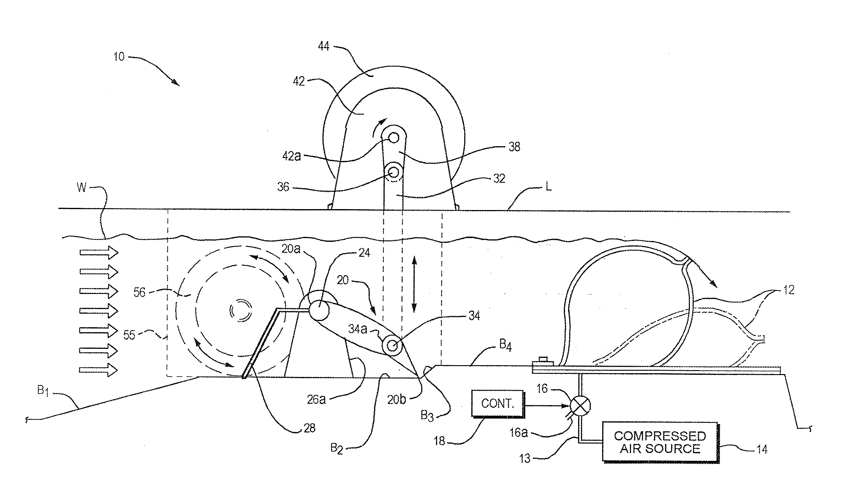
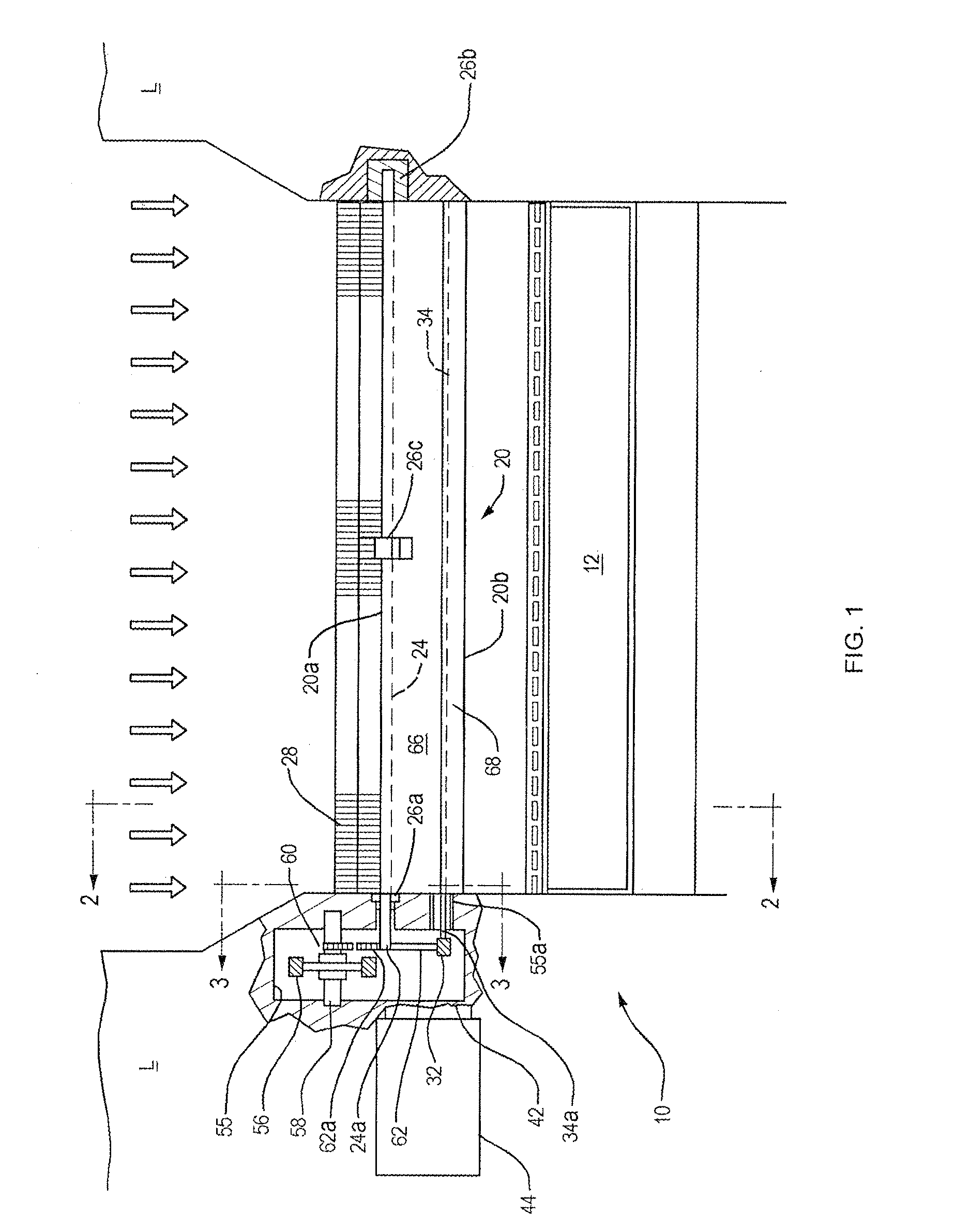
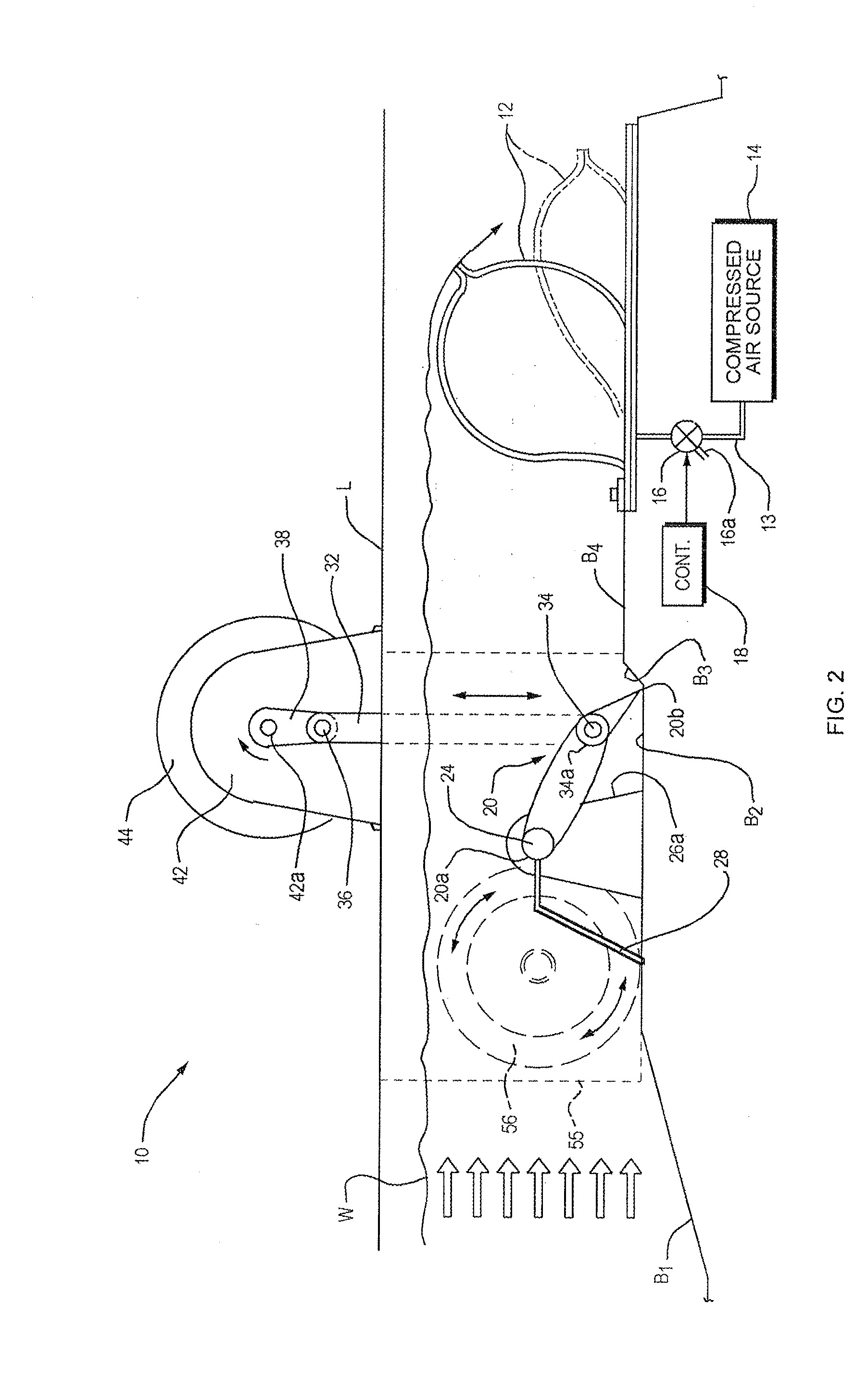
[0057]Refer now to FIGS. 1 and 2 of the drawings which show my apparatus, indicated generally at 10, as adapted to extract useful power from a relatively low pressure head, open shallow water source such as a river or stream, low head being defined as less than 10 meters. Apparatus 10 is mounted on the land L at opposite sides of a river whose water W flows in the direction of the arrows. Preferably, the bed of the river is prepared to receive the apparatus by profiling it is shown in FIG. 2 such that there is an incline B1 leading to a level area B2 directly under the apparatus. At the downstream edge of area B2, the bed steps up at B3 to a second level area B4 which is the site of a conventional, inflatable dam 12.

[0058]The interior of dam 12 is connected by a pipe 13 to a compressed air source 14, the flow of air through pipe 13 being controlled by a remote controlled valve 16. In order to increase the level of the water W over the bed B2, the valve 16 is operated to connect sour...


PUM


Abstract

Power generation apparatus includes a wing-shaped blade having opposite sides, opposite ends and leading and trailing edges extending between those ends. A lift differential producing device in the blade produces a lift differential at the opposite sides of the blade and that device is switched so that one blade side or the other produces the greater lift. A blade shaft extends along an axis in the blade that is in close parallel relation to the leading edge of the blade and that shaft is fixed to move with the blade. Supports support the blade shaft so that the blade can be positioned in a fluid stream with the leading edge facing upstream and swing about the axis between first and second extreme positions on opposite sides of a neutral position, the blade shaft oscillating with the blade. A coordinating device coordinates the switching of the lift differential producing device with the swinging of the blade so that the switching occurs at the extreme positions of the blade. A method of generating power using the apparatus is also disclosed.

Description

RELATED APPLICATION[0001]This application claims the benefit of Provisional Application No. 60 / 876,600, filed Dec. 22, 2006.BACKGROUND OF THE INVENTION[0002]This invention relates to power generation apparatus employing one or more blades which move under the influence of a fluid stream to produce an output force capable of performing useful work. For example, the apparatus may be used to power a pump or to reciprocate or rotate a shaft. The invention relates especially to such apparatus whose blade(s) oscillates instead of rotates in the presence of a wind or water stream to produce an output torque for driving an electric generator to provide grid quality power to a utility grid or to a remote off grid community, for example. A method for generating power in this fashion is also part of my invention.[0003]Conventional hydro-electric power generators usually comprise large rotating element water turbines requiring their own power house and extensive civil engineering works, and whi...

Claims


Application Information

Patent Timeline
IPC IPC(8): F03B13/00F03B3/12
CPCE02B9/00F03B13/086F03B17/062F03D9/008F03D11/02Y02E10/725F05B2240/214Y02E10/22Y02E10/28Y02E10/722F05B2240/201F03D9/007F03D9/12F03D13/22F03D15/00F03D15/10F03D9/255Y02E10/20Y02E10/30Y02E10/72Y02E60/16Y02E70/30Y02P80/10
Inventor BIRKESTRAND, ORVILLE J.
Owner BIRKESTRAND ORVILLE J
Why Eureka
Try Eureka