Starter mechanism having a multi-stage plunger relay

a technology of plunger relay and starter mechanism, which is applied in the direction of electromagnetic relay details, electromagnets, cores/yokes, etc., can solve the problems of no longer being able to generate force in particular winding sections lying between, and consequently high noise generation, so as to achieve high magnetic force, simplify the control considerably, and avoid the need for complex power electronics

Inactive Publication Date: 2013-10-01
SEG AUTOMOTIVE GERMANY GMBH
View PDF33 Cites 3 Cited by
  • Summary
  • Abstract
  • Description
  • Claims
  • Application Information

AI Technical Summary

Benefits of technology

[0005]The starter mechanism according to example embodiments of the present invention allows a low-noise coupling of the starter pinion to the ring gear of the combustion engine without requiring particularly high currents and, therefore, without the need for complex power electronics. Furthermore, the starter mechanism according to example embodiments of the present invention does not require a pulse-width control, which simplifies the control considerably. The plunger relays used according to example embodiments of the present invention are not restricted to electromagnets having low inductivity; instead, windings having a high number of windings may be used, which generate a high magnetic force even at low currents.
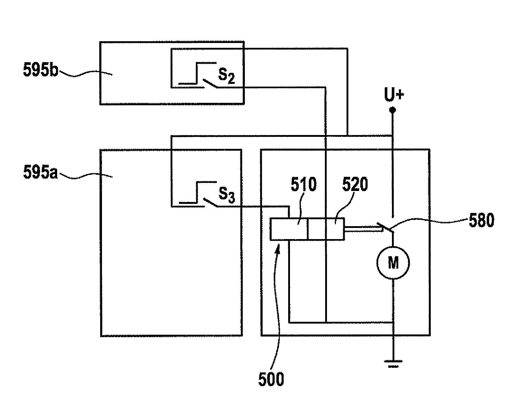
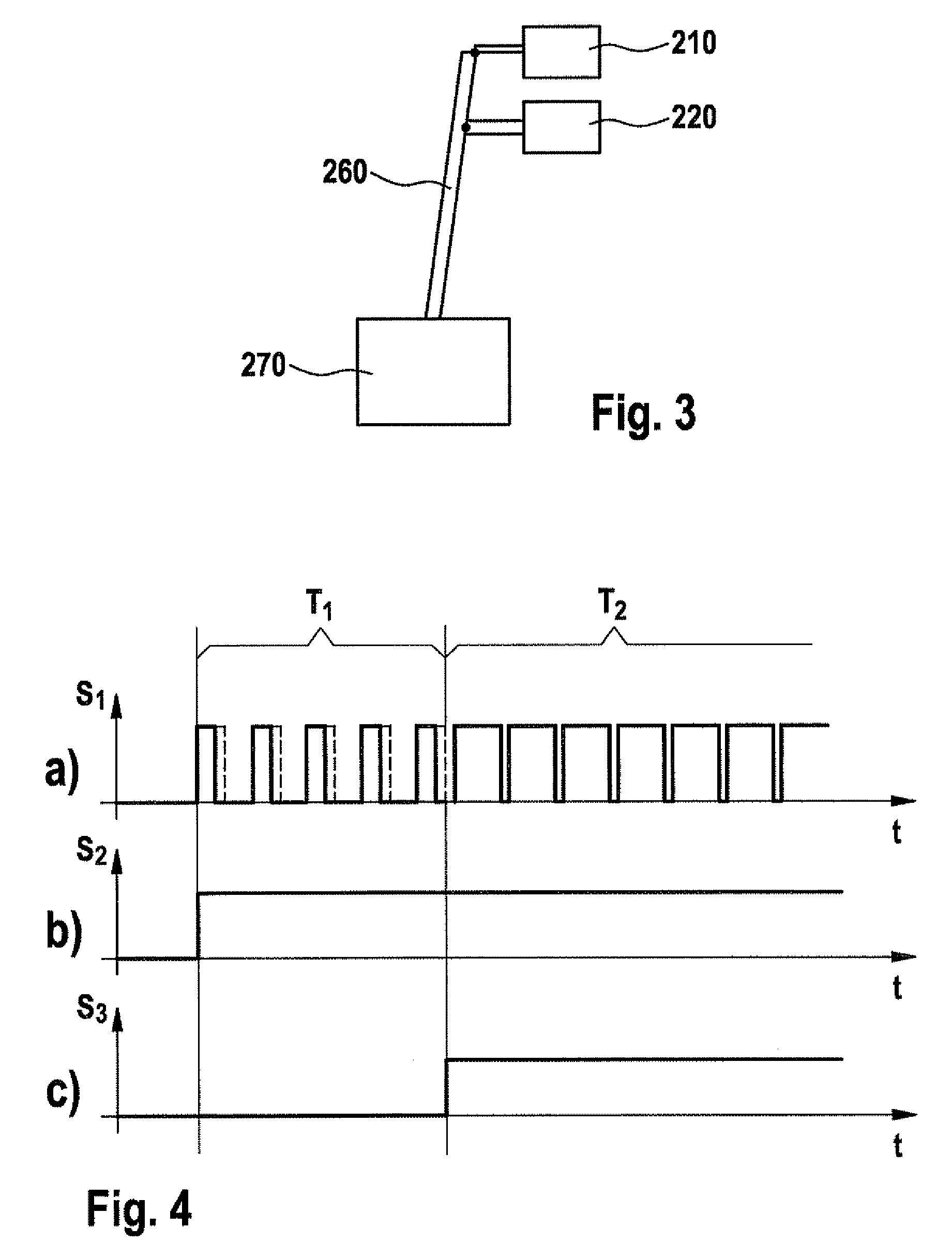
[0021]In example embodiments of the method, the actuation of the clutch includes the supply of current and / or voltage to a number of winding sections, the number of winding sections increasing during the startup phase. Therefore, only one of the two winding sections is able to be supplied with current in a first section of the startup phase, whereas both winding sections, i.e., the entire winding, are / is supplied with current in a second phase of the startup operation. This causes the solenoid actuator device to produce a higher magnetic force in the second phase than in the first phase, which prevents knocking and thereby reduces the noise generation. As an alternative, initially a higher lifting force may be produced according to the energization, which is followed by a phase having a lower lifting force, the number of energized solenoid actuators being modified accordingly.
[0028]In the control of the solenoid actuators, e.g., by the control device, it is also possible to consider the temperature, which is detected via an NTC element, in order to compensate the temperature-dependent behavior of the solenoid actuators, preferably by modifying the length or the start instants and the instants of the first and second phase of the startup operation. Since the internal resistance and thus the generated lifting force changes with the temperature, this makes it possible to provide the overall lifting force temperature independently.
[0030]As a further safety measure, each solenoid actuator or each winding section may have a separate supply feed, so that in an operation in the engine compartment in which the supply feed can also be omitted, a minimum lifting force is ensured even if one supply line is malfunctioning. In one further development, the engine electronics of the motor vehicle controls the triggering of the startup operation, and an additional separate start-stop control device implements the individual control of the solenoid actuators. The start-stop control device may preferably be triggered by an additional triggering mechanism, so that the starting function is still ensured even when the engine electronics malfunctions. In the same way the start-stop control device is able to be bridged with the aid of an external control, so that the engine electronics control the solenoid actuators directly. This ensures that the combustion engine is able to be started even without the afore-described two- or multi-stage control of the solenoid actuators.

Problems solved by technology

Especially in the case of hybrid engines in which the combustion engine is also regularly switched on and off during the operation, the noise generation is consequently high.
Furthermore, one winding element may be short-circuited with one tap, and / or two taps with each other, so that the particular winding section lying in-between is no longer available for the force generation.
This produces a redundancy, which permits the startup of the combustion engine even when one solenoid actuator or one winding section is not available.

Method used


Image

  • Starter mechanism having a multi-stage plunger relay
  • Starter mechanism having a multi-stage plunger relay
  • Starter mechanism having a multi-stage plunger relay

Examples


Embodiment Construction

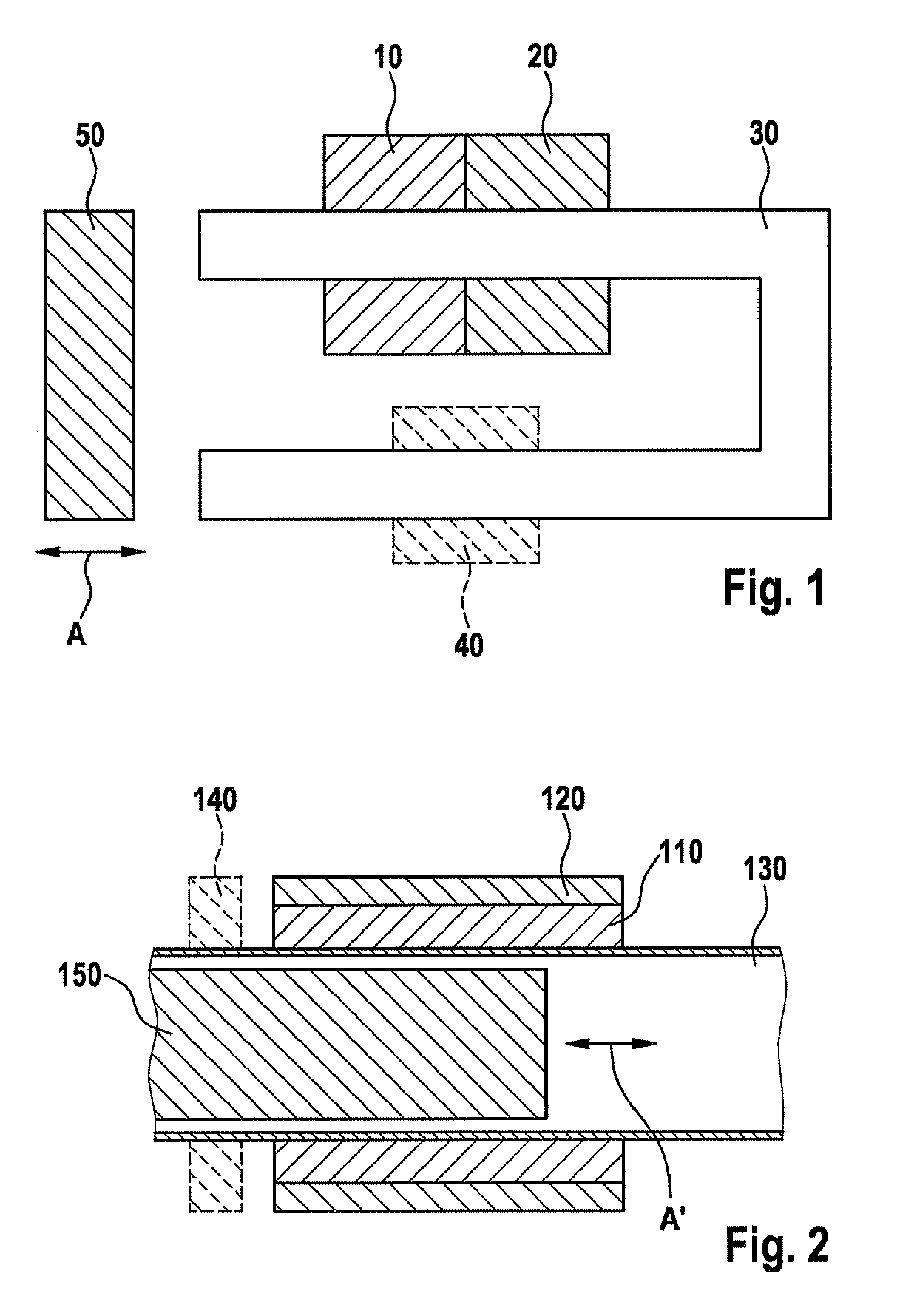
[0040]FIG. 1 shows a basic representation of the plunger relay according to an example embodiment of the present invention. The plunger relay includes a first solenoid actuator 10 and a second solenoid actuator 20, which are wound next to each other around a yoke 30. Yoke 30 includes one side that has the same longitudinal axis as the two cylindrically shaped solenoid actuators 10 and 20. First solenoid actuator 10 directly abuts second solenoid actuator 20, but it is also possible for a gap to exist between these two. Yoke 30 is made of a material that has high relative magnetic permeability and which thus collects the magnetic field generated by first solenoid actuator 10 and second solenoid actuator 20. The yoke includes a second side, which forms a U-shape with the first side via a crosspiece. The second side is enclosed by an additional third magnet 40 whose magnetic field likewise acts on yoke 30. Shown at the open end of the U-shaped yoke is a movable actuating element 50, wh...


PUM


Abstract

A plunger relay includes a movable actuating element on which a first solenoid actuator is acting in force-transmitting manner. The plunger relay has at least one second solenoid actuator, which is acting on the same movable actuating element in force-transmitting manner, and whose magnetic force is able to be set independently of the magnetic force of the first solenoid actuator.

Description

FIELD OF THE INVENTION[0001]The present invention is based on a starter mechanism for internal combustion engines having a pinion-engaging relay for the controlled coupling of the electric starter with the internal combustion engine.BACKGROUND INFORMATION[0002]Pinion starters in which a starter pinion engages with the ring gear of the internal combustion engine by means of a solenoid actuator during the startup operation are already known. When reaching an engaged end position, i.e., when fully meshing with the ring gear of the internal combustion engine, the pinion closes a contact bridge in the solenoid actuator. By closing the contact bridge the electric starter motor is supplied with current. Once the internal combustion engine has been started, the solenoid actuator is switched off, so that the pinion disengages from the ring gear of the combustion engine and the electric starter motor is therefore no longer coupled to the internal combustion engine.[0003]In conventional starte...

Claims


Application Information

Patent Timeline
Patent Type & Authority Patents(United States)
IPC IPC(8): H01H50/44F16K31/06F02N11/08
CPCF02N11/087F02N15/067F16K7/02H01H50/44H01H51/065F02N2011/0892H01F7/16H01F2007/1692H01H47/06H01H47/08
Inventor HEUSEL, JOCHENNEUBURGER, MARTINKNORR, TORSTEN
Owner SEG AUTOMOTIVE GERMANY GMBH
Why Eureka
Try Eureka