Starter mechanism having a multi-stage plunger relay

a technology of plunger relay and starter mechanism, which is applied in the direction of electromagnetic relay details, electromagnets, cores/yokes, etc., can solve the problems of no longer being able to generate force in particular winding sections lying between, and consequently high noise generation, so as to achieve high magnetic force, simplify the control considerably, and avoid the need for complex power electronics

Inactive Publication Date: 2010-05-27
SEG AUTOMOTIVE GERMANY GMBH
View PDF21 Cites 4 Cited by
  • Summary
  • Abstract
  • Description
  • Claims
  • Application Information

AI Technical Summary

Benefits of technology

[0005]The starter mechanism according to example embodiments of the present invention allows a low-noise coupling of the starter pinion to the ring gear of the combustion engine without requiring particularly high currents and, therefore, without the need for complex power electronics. Furthermore, the starter mechanism according to example embodiments of the pr

Problems solved by technology

Especially in the case of hybrid engines in which the combustion engine is also regularly switched on and off during the operation, the noise generation is consequently high.
Furthermore, one winding element may be short-circuited with one tap, and/or two taps with e

Method used


Image

  • Starter mechanism having a multi-stage plunger relay
  • Starter mechanism having a multi-stage plunger relay
  • Starter mechanism having a multi-stage plunger relay

Examples


Embodiment Construction

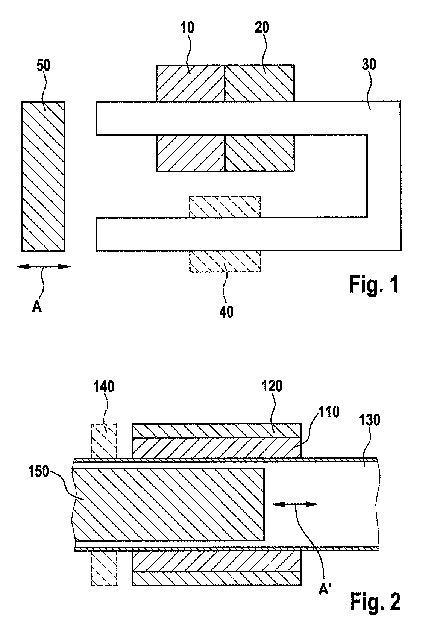
[0040]FIG. 1 shows a basic representation of the plunger relay according to an example embodiment of the present invention. The plunger relay includes a first solenoid actuator 10 and a second solenoid actuator 20, which are wound next to each other around a yoke 30. Yoke 30 includes one side that has the same longitudinal axis as the two cylindrically shaped solenoid actuators 10 and 20. First solenoid actuator 10 directly abuts second solenoid actuator 20, but it is also possible for a gap to exist between these two. Yoke 30 is made of a material that has high relative magnetic permeability and which thus collects the magnetic field generated by first solenoid actuator 10 and second solenoid actuator 20. The yoke includes a second side, which forms a U-shape with the first side via a crosspiece. The second side is enclosed by an additional third magnet 40 whose magnetic field likewise acts on yoke 30. Shown at the open end of the U-shaped yoke is a movable actuating element 50, wh...


PUM


Abstract

A plunger relay includes a movable actuating element on which a first solenoid actuator is acting in force-transmitting manner. The plunger relay has at least one second solenoid actuator, which is acting on the same movable actuating element in force-transmitting manner, and whose magnetic force is able to be set independently of the magnetic force of the first solenoid actuator.

Description

FIELD OF THE INVENTION[0001]The present invention is based on a starter mechanism for internal combustion engines having a pinion-engaging relay for the controlled coupling of the electric starter with the internal combustion engine.BACKGROUND INFORMATION[0002]Pinion starters in which a starter pinion engages with the ring gear of the internal combustion engine by means of a solenoid actuator during the startup operation are already known. When reaching an engaged end position, i.e., when fully meshing with the ring gear of the internal combustion engine, the pinion closes a contact bridge in the solenoid actuator. By closing the contact bridge the electric starter motor is supplied with current. Once the internal combustion engine has been started, the solenoid actuator is switched off, so that the pinion disengages from the ring gear of the combustion engine and the electric starter motor is therefore no longer coupled to the internal combustion engine.[0003]In conventional starte...

Claims


Application Information

Patent Timeline
IPC IPC(8): F02N15/02F02N11/08H01F7/08
CPCF02N11/087F02N15/067F02N2011/0892F16K7/02H01H51/065H01F2007/1692H01H47/06H01H47/08H01H50/44H01F7/16
Inventor HEUSEL, JOCHENNEUBURGER, MARTINKNORR, TORSTEN
Owner SEG AUTOMOTIVE GERMANY GMBH
Why Eureka
Try Eureka