Premixed Combustion Burner of Gas Turbine Technical Field

a technology of combustion burner and gas turbine, which is applied in the combustion process, hot gas positive displacement engine plant, lighting and heating apparatus, etc., can solve the problem of not having satisfactory performance of premixed combustion burner, and achieve the effect of preventing backfire and uniform fuel concentration

Active Publication Date: 2008-06-26
MITSUBISHI POWER LTD
View PDF17 Cites 52 Cited by
  • Summary
  • Abstract
  • Description
  • Claims
  • Application Information

AI Technical Summary

Benefits of technology

[0044]According to the present invention, the angle formed by the tangent to the average camber line of the swirl vane at the rear edge of the swirl vane and the axis line extending along the axial direction of the fuel nozzle is 0 to 10 degrees on the inner peripheral side of the rear edge of the swirl vane, and the angle is larger (25 to 35 degrees) on the outer peripheral side of the rear edge of the swirl vane than the angle on the inner peripheral side of the rear edge of the swirl vane. Thus, whether on the inner peripheral side or on the outer peripheral side of the air passage, the flow velocity of air becomes uniform, the occurrence of backfire can be prevented, and the fuel concentration becomes uniform.
[0045]According to the present invention, moreover, the clearance is provided between the outer peripheral side end surface of the swirl vane and the inner peripheral surface of the burner tube. Thus, a vortex air flow is produced by the action of a leakage flow, which passes through the clearance and flows from the vane dorsal surface to the vane ventral surface, and a flow in the axial direction, and this vortex air flow can promote the mixing of the fuel and air.

Problems solved by technology

The premixed combustion burner having swirl vanes on the outer peripheral surface of a premixing fuel nozzle has hitherto been present, but there has been no premixed combustion burner with satisfactory performance which can

Method used


Image

  • Premixed Combustion Burner of Gas Turbine Technical Field
  • Premixed Combustion Burner of Gas Turbine Technical Field
  • Premixed Combustion Burner of Gas Turbine Technical Field

Examples


embodiment 1

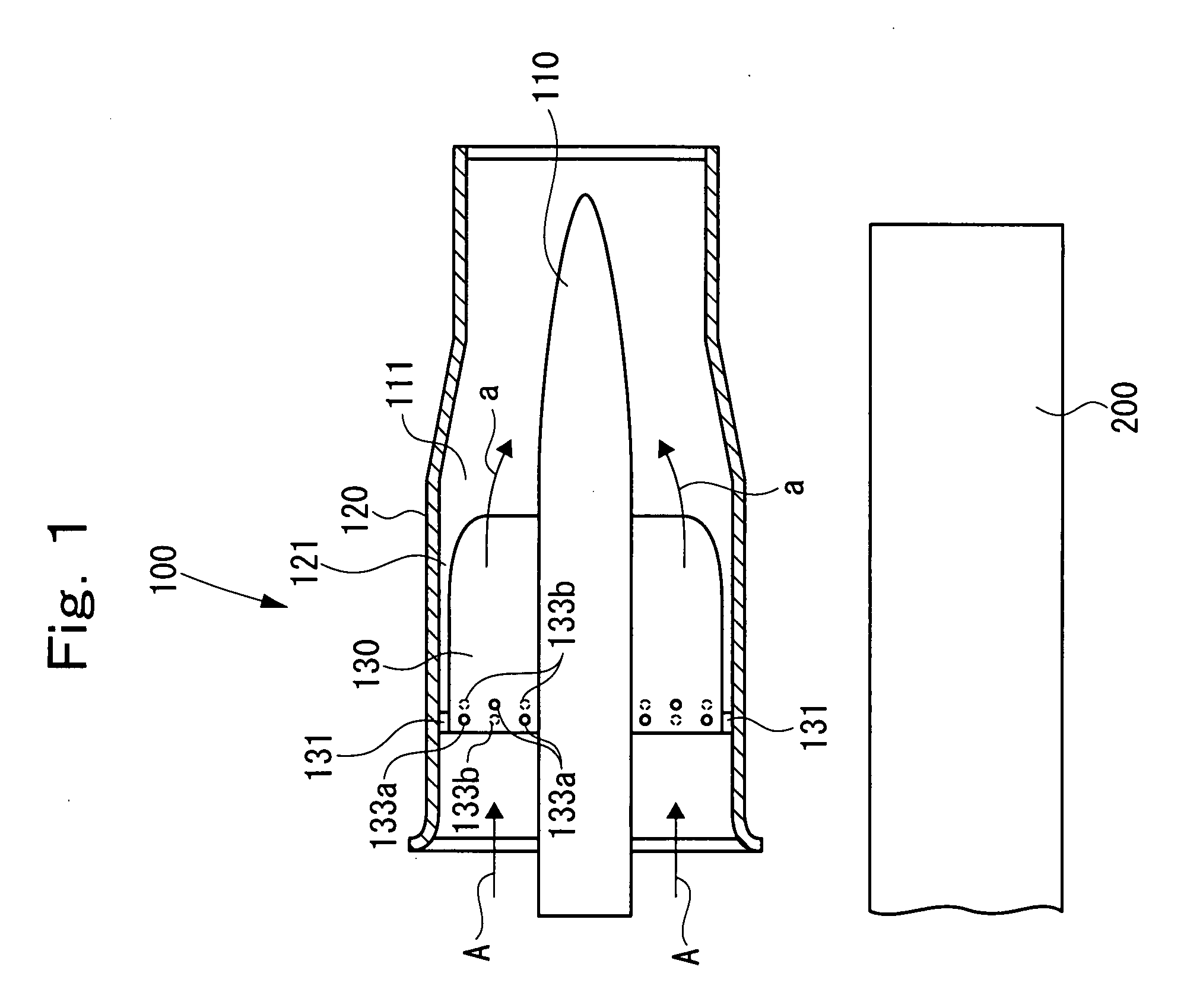
[0073]A plurality of premixed combustion burners 100 of a gas turbine according to Embodiment 1 of the present invention are arranged to surround the periphery of a pilot combustion burner 200, as shown in FIG. 1. A pilot combustion nozzle, although not shown, is built into the pilot combustion burner 200.

[0074]The premixed combustion burners 100, and the pilot combustion burner 200 are arranged within the inner tube of the gas turbine.

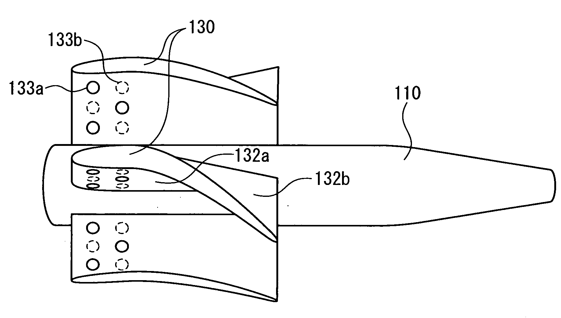
[0075]The premixed combustion burner 100 is composed of a fuel nozzle 110, a burner tube 120, and a swirl vane (swirler vane) 130 as main members.

[0076]The burner tube 120 is disposed to be concentric with the fuel nozzle 110 and to encircle the fuel nozzle 110. Thus, a ring-shaped air passage 111 is formed between the outer peripheral surface of the fuel nozzle 110 and the inner peripheral surface of the burner tube 120.

[0077]Compressed air A flows through the air passage 111 from its upstream side (left-hand side in FIG. 1) toward its downstream sid...

embodiment 2

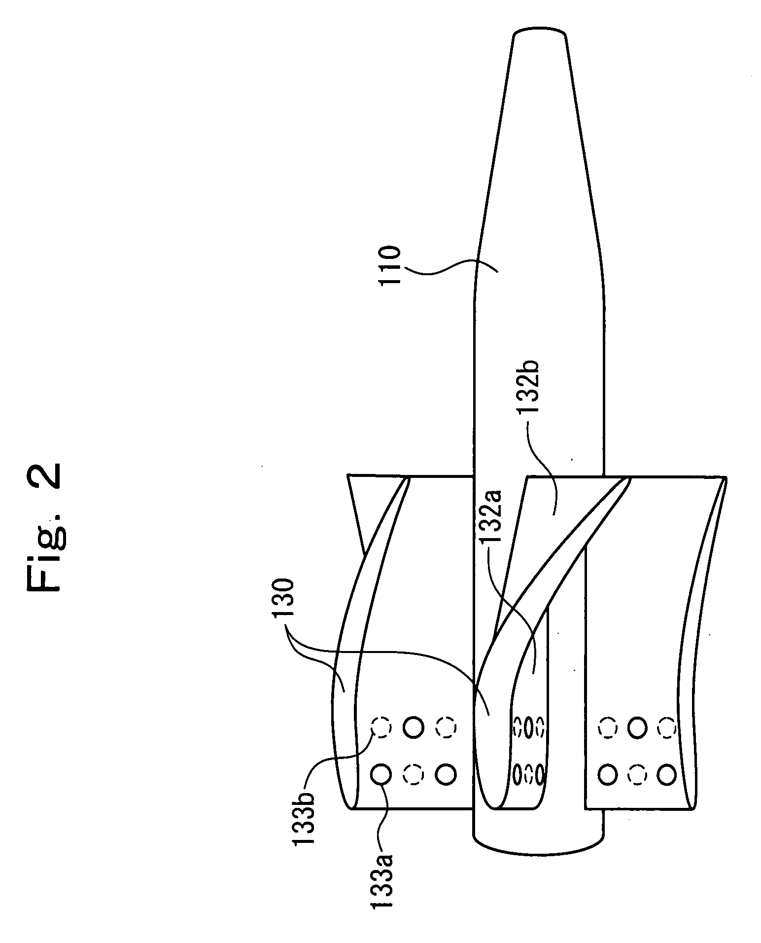
[0146]In the above-described Embodiment 1, the swirl vane 130 is configured, as shown in FIG. 2, such that the angle formed by the tangent to the average camber line of the swirl vane 130 at the rear edge of the swirl vane 130 and the axis line extending along the axial direction of the fuel nozzle 100 is 0 to 10 degrees on the inner peripheral side of the rear edge of the swirl vane 130, and is 25 to 35 degrees on the outer peripheral side of the rear edge of the swirl vane 130.

[0147]In Embodiment 2, there is adopted the swirl vane 130 configured, as shown in FIG. 10, such that the angle formed by the tangent to the average camber line of the swirl vane 130 at the rear edge of the swirl vane 130 and the axis line extending along the axial direction of the fuel nozzle 110 is rendered the same for the inner peripheral side and the outer peripheral side of the rear edge of the swirl vane 130.

[0148]The swirl vanes 130, in each of which the angle formed by the tangent to the average cam...


PUM


Abstract

A fuel nozzle 110 having a plurality of swirl vane 130 on an outer peripheral surface thereof is installed within a burner tube 120, with a clearance 121 being provided. Each swirl vane 130 progressively curves from an upstream side toward a downstream side (inclines along a circumferential direction) in order to swirl compressed air A flowing through an air passage 111 to form a swirl air flow a. Here, curvature of each swirl vane 130 is greater on its outer peripheral side than on its inner peripheral side. By suppressing occurrence of an air streamline heading from the inner peripheral side toward the outer peripheral side, therefore, flow velocity on the inner peripheral side and flow velocity on the outer peripheral side become equal, thus preventing flashback on the inner peripheral side. Moreover, a swirl imparting force in the circumferential direction per unit length on the inner peripheral side and that on the outer peripheral side become equal, equalizing the fuel concentration on the inner peripheral side and the fuel concentration on the outer peripheral side. Furthermore, a leakage flow, which passes from the vane dorsal surface side through the clearance 121 and leaks to the vane ventral surface side, generates a vortex air flow, promoting mixing of fuel and air.

Description

TECHNICAL FIELD[0001]This invention relates to a premixed combustion burner of a gas turbine. The present invention is contrived to be capable of effectively premixing a fuel and air to form a fuel gas of a uniform concentration, and uniformizing the flow velocity of the fuel gas, thereby preventing backfire reliably.BACKGROUND ART[0002]A gas turbine used in power generation, etc. is composed of a compressor, a combustor, and a turbine as main members. The gas turbine often has a plurality of combustors, and mixes air, which is compressed by the compressor, with a fuel supplied to the combustors, and burns the mixture in each combustor to generate a high temperature combustion gas. This high temperature combustion gas is supplied to the turbine to drive the turbine rotationally.[0003]An example of the combustor of a conventional gas turbine will be described with reference to FIG. 11.[0004]As shown in FIG. 11, a plurality of combustors 10 of the gas turbine are arranged annularly in...

Claims


Application Information

Patent Timeline
Patent Type & Authority Applications(United States)
IPC IPC(8): F23R3/14
CPCF23R3/286F23R3/14
Inventor ISHIZAKA, KOICHIITO, EISAKUTANIMURA, SATOSHI
Owner MITSUBISHI POWER LTD
Why Eureka
Try Eureka