

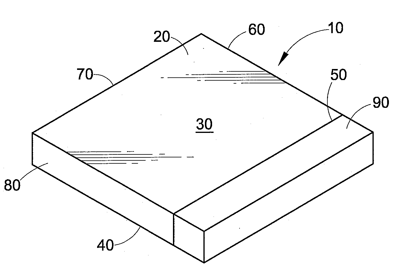
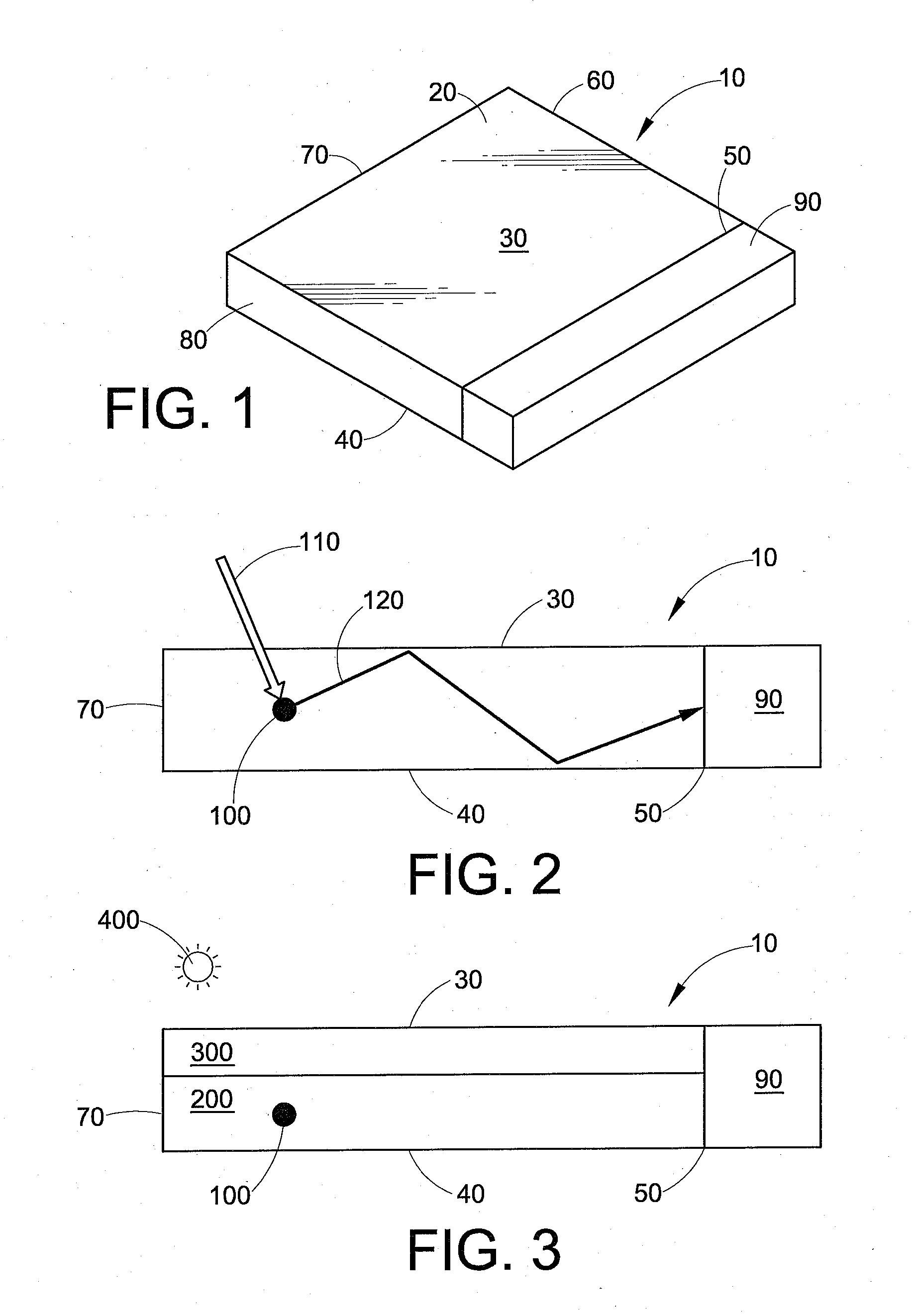
Luminescent solar collector
a solar collector and solar energy technology, applied in solar heat systems, pv power plants, light and heating equipment, etc., can solve the problems of limiting the application of lscs, aesthetically unpleasing, and technical problems
- Summary
- Abstract
- Description
- Claims
- Application Information
AI Technical Summary
Benefits of technology
Problems solved by technology
Method used
Image

Examples
examples
Reference Example
[0128]A polycarbonate LSC equipped with two silicon photocells is able to convert 3-3.5% of the solar light into electricity. A reference sample containing polycarbonate with 0.05 weight percent heat stabilizer and 0.02 weight percent Lumogen® F Red 300 (from BASF) was compounded and molded into a plaque of 3.2 mm thickness. The sample was subjected to artificial weathering according to ISO4892-2A corresponding to a time of 3172 hours and the haze was measured according to ASTM D1003-00. The edge emission, a measure for optical and electrical efficiency, was also measured. The results are shown in Table 1.
TABLE 1TimeHaze (%)Edge Emission (W / m2) 0 hours16.93233172 hours>80279
Single Layer Example
[0129]Next, several plaques were produced of polyester-polycarbonate resin having various amounts of ITR resin and UV agent, as shown in Table 2. These plaques had a thickness of 2.5 mm. These plaques were also weathered (ISO4892-2A) corresponding to a time of 2500 hours, the...
PUM
 Abstract
Description
Claims
Application Information