System, method, and apparatus for control input prediction and state verification of fluidic vectoring exhaust in high performance aircraft

Active Publication Date: 2008-06-26
LOCKHEED MARTIN CORP
View PDF11 Cites 8 Cited by
  • Summary
  • Abstract
  • Description
  • Claims
  • Application Information

AI Technical Summary

Benefits of technology

[0010]Overall, the control system derives a desired vector state, then predicts and sets the fluidic injection input required to produce the desired vector state. Finally, a vectored state verification routine is used to determine the resulting vector state for feedback to the control system. The invention offers a robust solution that accomplishes a mechanically non-invasive, fluidic nozzle vector control in a next generation, advanced nozzle configuration. In addition, the feedback feature allows compensation for valve wear, leakage, etc.

Problems solved by technology

However, the need for aggressive next-generation designs with complex geometric shaping has placed an emphasis on moving away from mechanical systems.
Consequently, a significant problem encountered during the development of fluidic vectoring nozzles has centered on how to verify the vector state of the exhaust plume.

Method used


Image

  • System, method, and apparatus for control input prediction and state verification of fluidic vectoring exhaust in high performance aircraft
  • System, method, and apparatus for control input prediction and state verification of fluidic vectoring exhaust in high performance aircraft
  • System, method, and apparatus for control input prediction and state verification of fluidic vectoring exhaust in high performance aircraft

Examples


Embodiment Construction

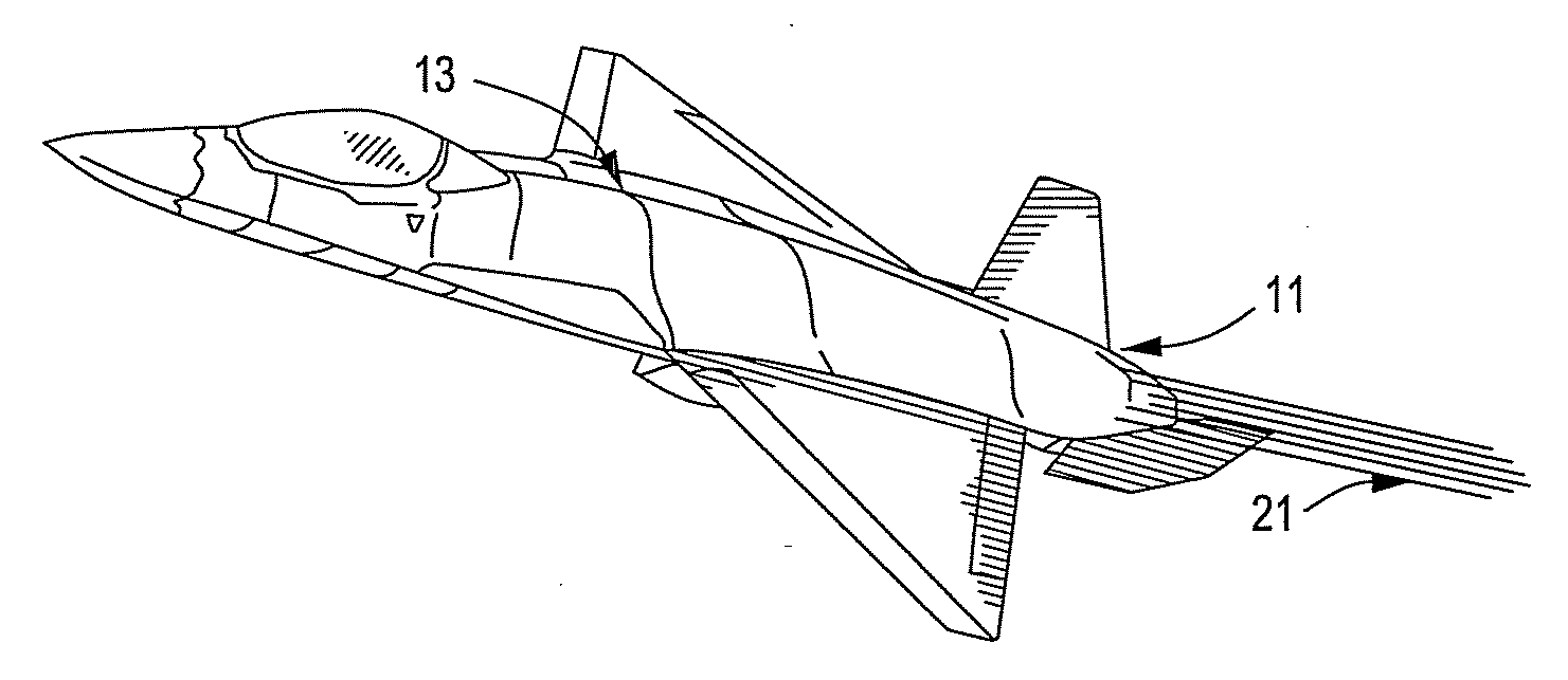
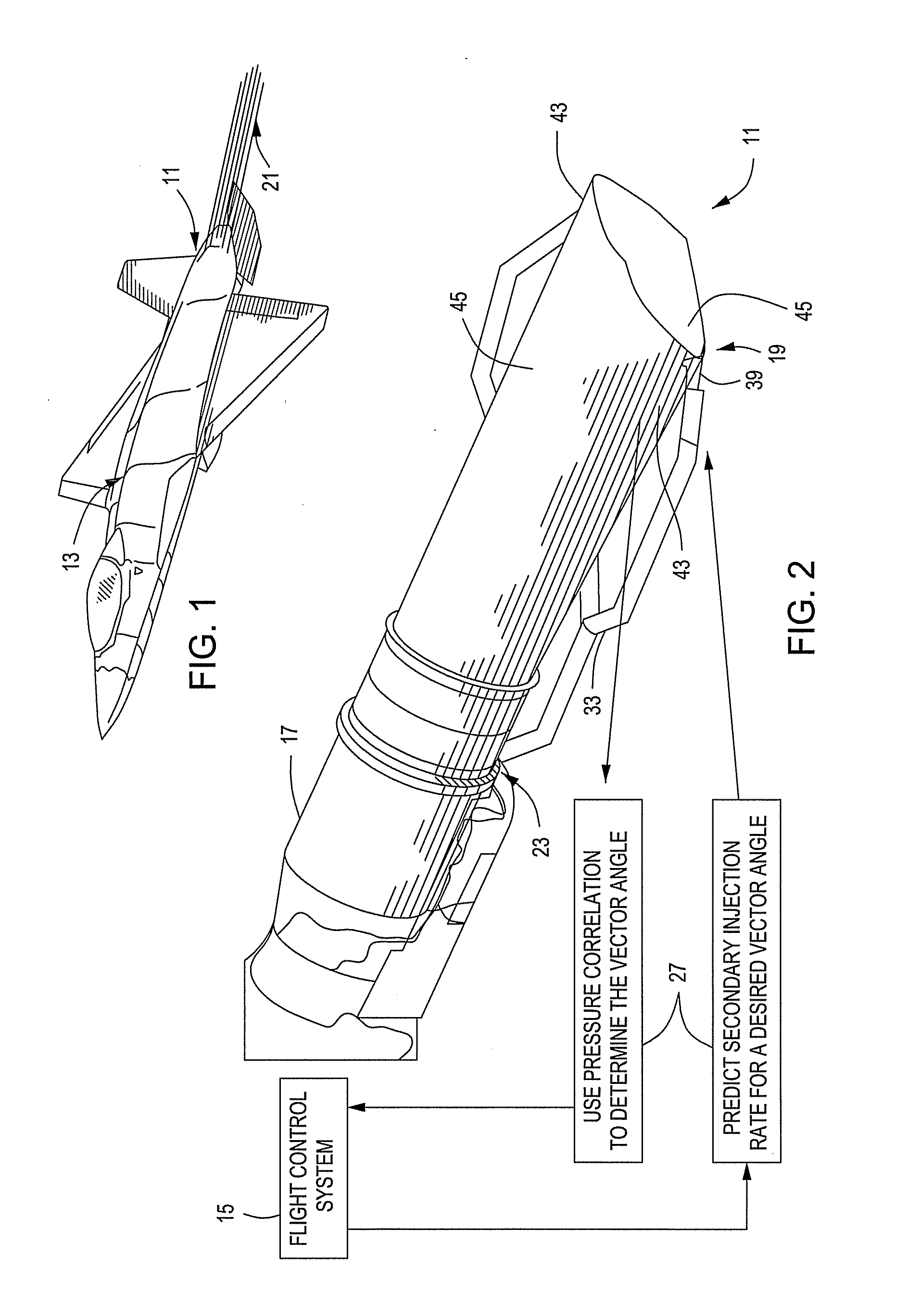
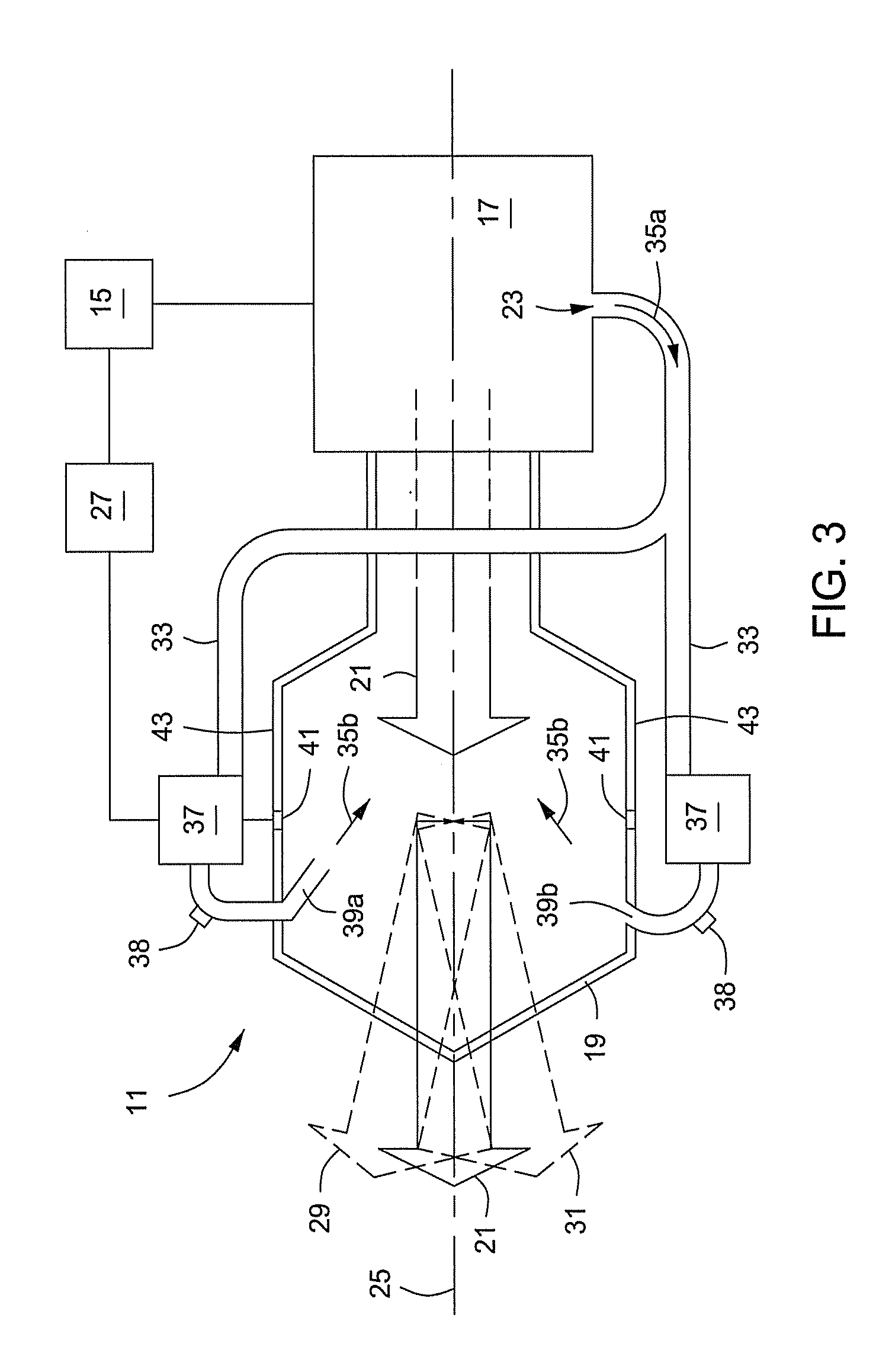
[0017]Referring to FIGS. 1-4, one embodiment of a system, method, and apparatus for a fluidic vectoring exhaust system is shown. The invention is well suited for high performance aircraft applications, such as the system 11 on aircraft 13 depicted in FIG. 1. Additional details of the invention are illustrated in FIGS. 2 and 3, including a flight control system 15 for controlling and monitoring various flight sub-systems, parameters, etc., of the aircraft 13. For example, flight control system 15 may be integrated with the control system for an engine 17 and nozzle 19. In the embodiment shown, nozzle 19 is a single nozzle in a mechanically “fixed” configuration meaning that it has no moving parts. Nozzle 19 is located downstream from the engine 17 for releasing an exhaust plume 21 (FIGS. 1 and 3) from the engine 17. Engine bleed port(s) 23 provide high pressure bleed air from the engine 17 for use in a fluidic off-take or duct system 33. In the embodiment shown, nozzle 19 defines a c...


PUM


Abstract

A non-invasive system, method, and apparatus for control input prediction and state verification of an aircraft's fluidic vectoring exhaust is disclosed. The control system derives a desired vector state, then predicts and sets the fluidic injection input required to produce the desired vector state. A vectored state verification routine is used to determine the resulting vector state for feedback to the control system.

Description

BACKGROUND OF THE INVENTION[0001]1. Technical Field[0002]The present invention relates in general to directing the exhaust of an aircraft to improve its agility in flight and, in particular, to an improved system, method, and apparatus for control input prediction and state verification of a high performance aircraft's fluidic vectoring exhaust system.[0003]2. Description of the Related Art[0004]The exhaust nozzles of conventional jet aircraft typically direct the exhaust flow along a central axis of the nozzle. In order to improve the agility of high performance aircraft, vectoring nozzles have been used to redirect the exhaust slightly off-axis. Historically, vectoring nozzles have used mechanical systems to redirect the exhaust flow. Such mechanical systems usually employ plates or the like that are located adjacent to the nozzle to channel the exhaust flow in the desired direction. However, the need for aggressive next-generation designs with complex geometric shaping has placed...

Claims


Application Information

Patent Timeline
IPC IPC(8): F02K1/15
CPCB64C15/02F02K1/008F05D2270/301F02K1/28F05D2270/051F02K1/15
Inventor BURGUN, ROB S.GINN, KERRY B.MILLER, DANIEL N.
Owner LOCKHEED MARTIN CORP
Why Eureka
Try Eureka