Method for rotary positive displacement pump protection

a positive displacement, pump technology, applied in the direction of rotary/oscillating piston pump components, machines/engines, liquid fuel engines, etc., can solve the problems of difficult to provide a robust pump protection solution while avoiding nuisance faults, and achieve the effect of increasing robustness and response time and avoiding nuisance faults

Inactive Publication Date: 2014-05-01
ITT MFG ENTERPRISES LLC
View PDF5 Cites 12 Cited by
  • Summary
  • Abstract
  • Description
  • Claims
  • Application Information

AI Technical Summary

Benefits of technology

[0011]The present invention provides new and unique techniques for protecting rotary positive displacement pumps, while differentiating between dangerous operating conditions such as dry running which can result in catastrophic damage if left to operate without intervention. Examples of rotary positive displacement pumps are internal or external gear pumps, lobe pumps, vane pumps and progressive cavity pumps. The methodology relies on two types of protection to increase robustness and response time. Providing a robust pump protection solution while avoiding nuisance faults can be difficult. In order to use power, or torque measurements to detect a dry run condition the following must be considered: power and torque varies with specific gravity, viscosity, differential pressure and speed changes. Speed is the easiest parameter to contend with as it can be measured directly. For varying temperature systems the power and torque comparisons must all be evaluated at a common specific gravity and viscosity. Therefore power and torque readings are corrected to rated conditions for specific gravity and viscosity changes before any evaluation is done. This can be achieved by entering the specific gravity and viscosity vs. temperature curves in the controller. A simple temperature measuring device can then be used to correct power readings.

Problems solved by technology

Providing a robust pump protection solution while avoiding nuisance faults can be difficult.

Method used


Image

  • Method for rotary positive displacement pump protection
  • Method for rotary positive displacement pump protection
  • Method for rotary positive displacement pump protection

Examples


Embodiment Construction

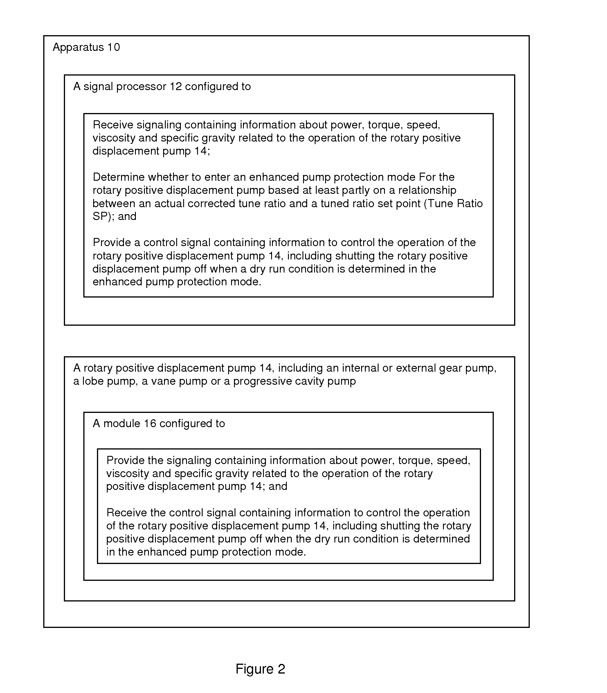
[0054]By way of example, as shown in FIG. 2, according to some embodiments, the present invention may take the form of apparatus 10 that includes a signal processor 12 configured to protect the operation a rotary positive displacement pump 14, e.g., which may include, or take the form of, an internal or external gear pump, a lobe pump, a vane pump or a progressive cavity pump.

[0055]The signal processor 12 may be configured to receive signaling containing information about power, torque, speed, viscosity and specific gravity related to the operation of the rotary positive displacement pump 14 and determine whether to enter an enhanced pump protection mode for the rotary positive displacement pump based at least partly on a relationship between an actual corrected tune ratio and a tuned ratio set point (Tune Ratio SP) else remain in the basic protection mode. The signal processor 12 may also be configured to provide a control signal containing information to control the operation of t...


PUM


Abstract

Techniques are provided for protecting a rotary positive displacement pump. The techniques include apparatus featuring a signal processor configured to receive signaling containing information about power, torque, speed, viscosity and specific gravity related to the operation of a pump; and determine whether to enter an enhanced pump protection mode for the rotary positive displacement pump based at least partly on a relationship between an actual corrected tune ratio and a tuned ratio set point (Tune Ratio SP). The signal processor may determine if the actual corrected tune ratio is less than or equal to the actual corrected tune ratio set point (Tune Ratio SP), and if so, then to enter the enhanced pump protection mode, else to continue to use a basic pump protection mode, and may also determine the actual corrected tune ratio based at least partly on a ratio of an actual corrected power (PAcorr) divided by a tuned corrected power (PTcorr) at a specific operating speed

Description

CROSS-REFERENCE TO RELATED APPLICATIONS[0001]This application claims benefit to provisional patent application Ser. No. 61 / 622,684, filed 11 Apr. 2012, which is hereby incorporated by reference in its entirety.BACKGROUND OF THE INVENTION[0002]1. Field of the Invention[0003]This application relates to a rotary positive displacement pump, such as an internal or external gear pump, a lobe pump, a vane pump or a progressive cavity pump; and more particularly, relates to techniques for protection, e.g., for a dry run condition, for such a rotary positive displacement pump.[0004]2. Brief Description of Related Art[0005]Many different types or kinds of pumps and external protective devices, including rotary positive displacement pumps with external protection devices, are known in the art. By way of example, some known external protection device disadvantages associated with the same and set forth below:[0006]One known device PMP 25, provided by a company named Load Controls, Inc. (Sturbri...

Claims


Application Information

Patent Timeline
Patent Type & Authority Applications(United States)
IPC IPC(8): F04C28/28
CPCF04C28/28F04C14/28F04C2270/052F04C2270/025F04C2270/03F04C2270/86
Inventor STAVALE, ANTHONY E.SEMIDEY, ROBERT
Owner ITT MFG ENTERPRISES LLC
Why Eureka
Try Eureka