
Valve assemblies for heating devices

a technology for heating devices and valve assemblies, applied in the direction of multiple way valves, candle holders, fluid pressure control, etc., can solve the problems of device and certain components thereof having various limitations and disadvantages

Inactive Publication Date: 2008-06-26
PROCOM HEATING
View PDF117 Cites 63 Cited by
  • Summary
  • Abstract
  • Description
  • Claims
  • Application Information

AI Technical Summary

Benefits of technology

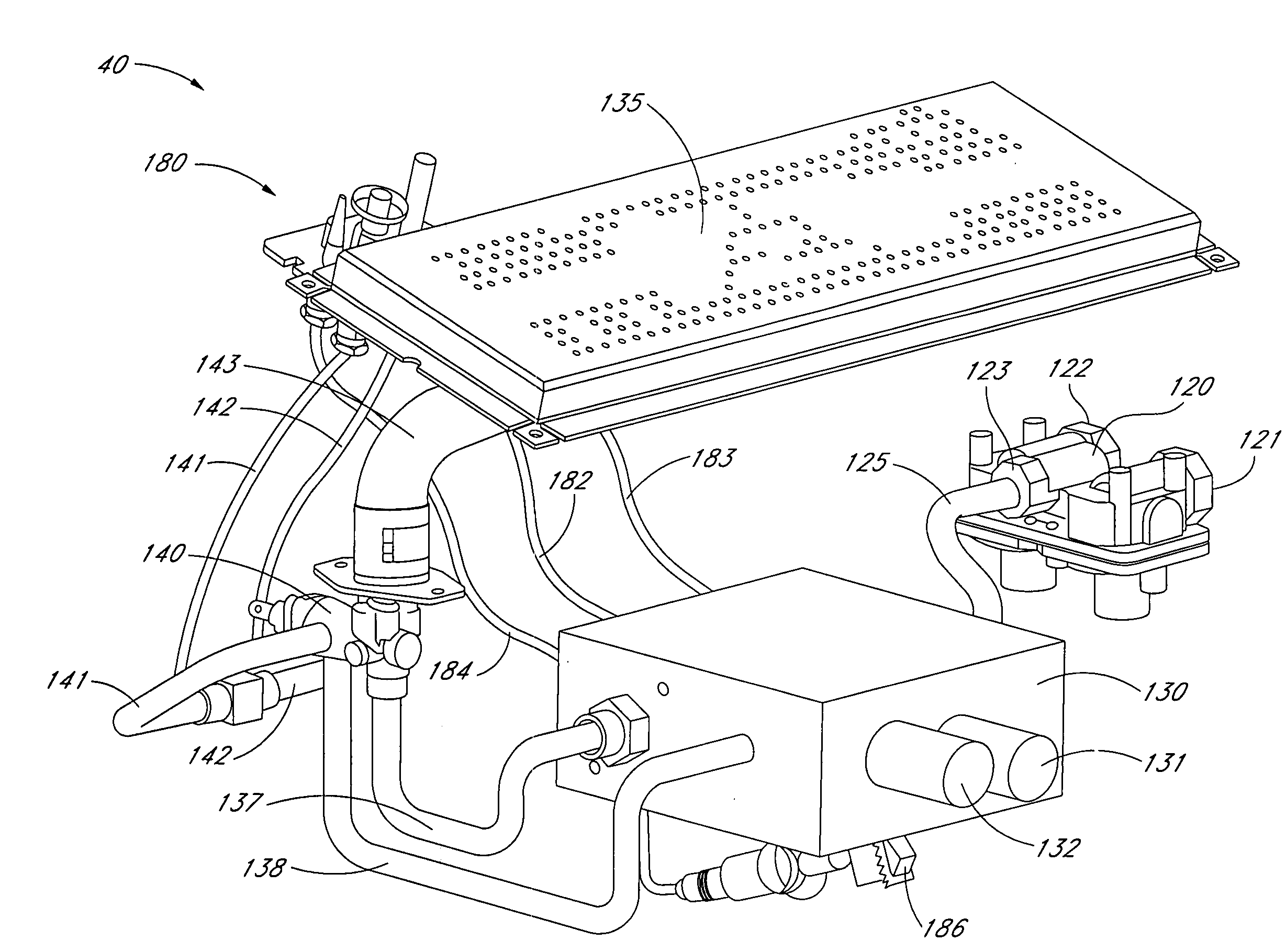
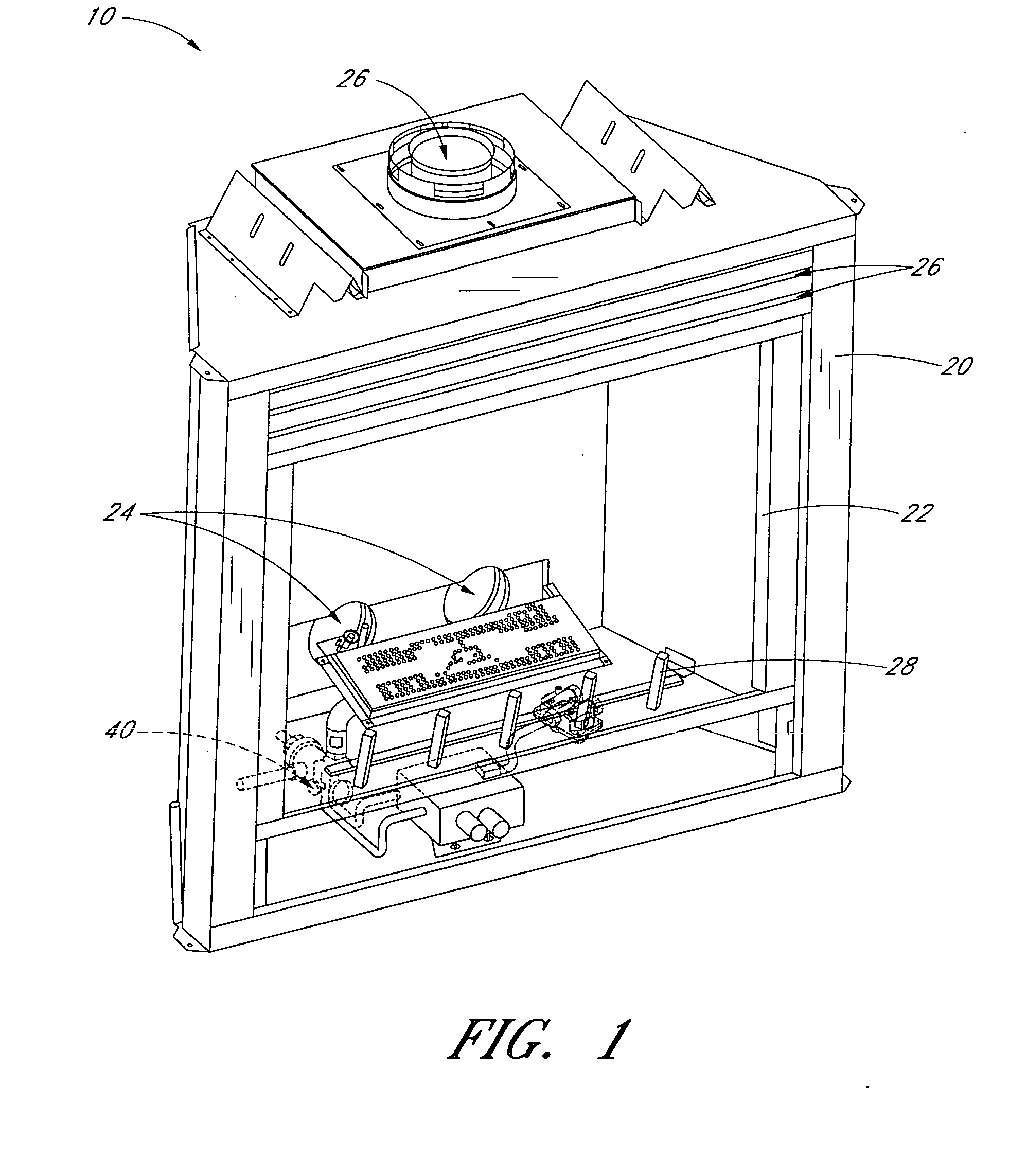
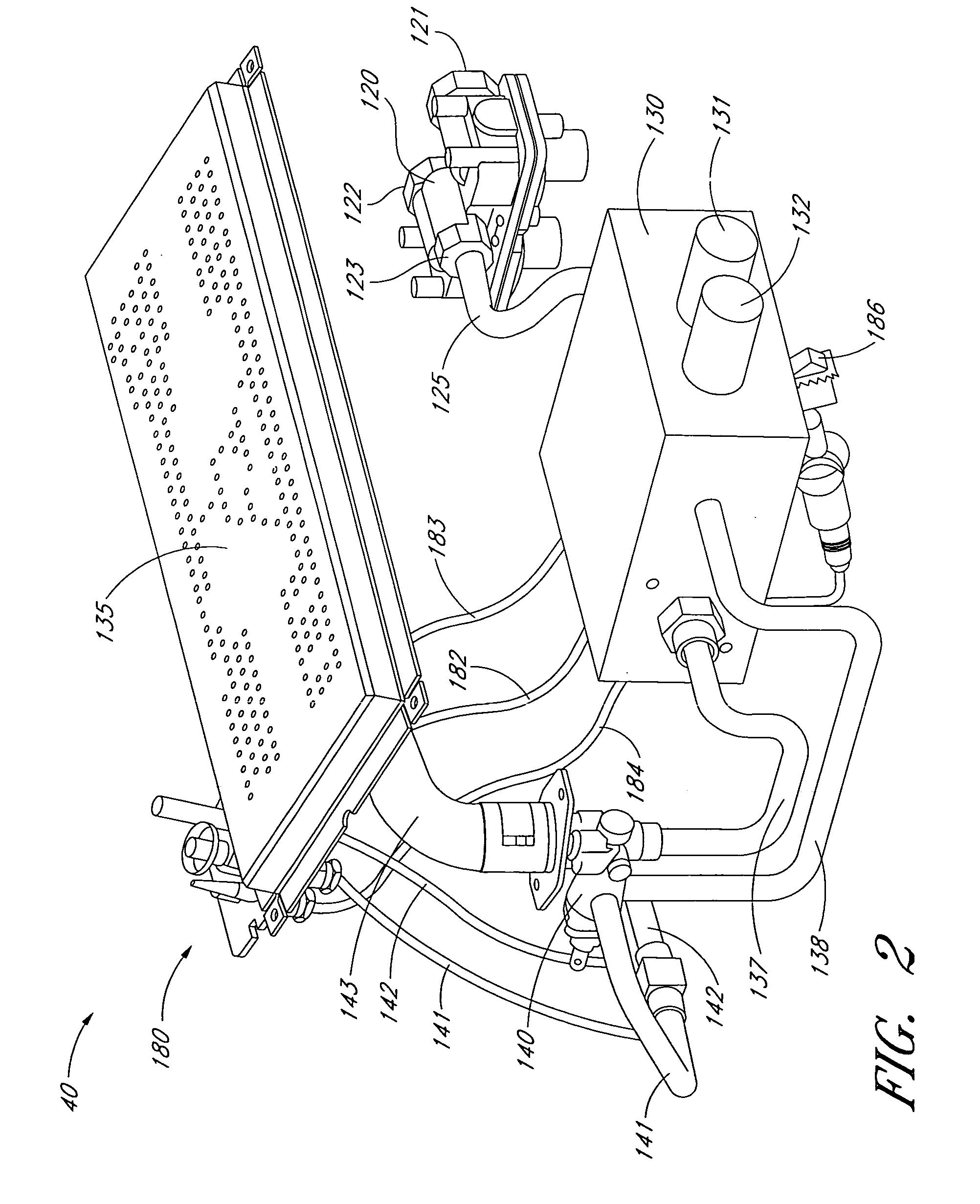
[0006]In certain embodiments, a valve assembly for a heating device includes a housing. The housing can define a first fuel input for receiving a fuel from a first fuel source or a second fuel source. The housing can further define a second fuel input for receiving a fuel from said first fuel source or said second fuel source. The housing can further define a first flow path, a second flow path, a third flow path, and a fourth flow path. The assembly can include a valve body configured to permit fluid communication between the first fuel input and the first flow path and between the second fuel input and the third flow path when in a first state. The valve body can be configured to permit fluid communication between the first fuel input and the second flow path and between the second fuel input and the fourth flow path when in a second state. The assembly can further include a mixing compartment in fluid communication with the first flow path, the second flow path and a burner. The compartment can define one or more channels through which air can flow to mix with fuel delivered to the compartment via the first flow path or the second flow path.
[0007]In certain embodiments, a valve assembly includes a housing. The housing can define a first input for receiving fuel from a first fuel source or from a second fuel source. The housing can further define a first output for dispensing fuel received f

Problems solved by technology

However, such devices and certain components thereof have various limitations and disadvantages

Method used


Image

  • Valve assemblies for heating devices
  • Valve assemblies for heating devices
  • Valve assemblies for heating devices

Examples


Embodiment Construction

[0050]Many varieties of space heaters, wall heaters, stoves, fireplaces, fireplace inserts, gas logs, and other heat-producing devices employ combustible fluid fuels, such as liquid propane and natural gas. The term “fluid,” as used herein, is a broad term used in its ordinary sense, and includes materials or substances capable of fluid flow, such as, for example, one or more gases, one or more liquids, or any combination thereof. Fluid-fueled units, such as those listed above, generally are designed to operate with a single fluid fuel type at a specific pressure or within a range of pressures. For example, some fluid-fueled heaters that are configured to be installed on a wall or a floor operate with natural gas at a pressure in a range from about 3 inches of water column to about 6 inches of water column, while others are configured to operate with liquid propane at a pressure in a range from about 8 inches of water column to about 12 inches of water column. Similarly, some gas fi...


PUM


Abstract

In certain embodiments, a valve assembly includes a housing. The housing can define a first fuel intake, a first fuel output, and a second fuel output. The assembly can include a valve member configured to direct fuel from the first fuel intake to either the first fuel output or the second fuel output. The assembly can further include a nozzle having a first portion and a second portion. The first portion of the nozzle can be in communication with the first fuel output, and the second portion of the nozzle can be in communication with the second fuel output. The assembly can include a compartment in communication with the nozzle, and can include one or more air intakes.

Description

CROSS-REFERENCE TO RELATED APPLICATIONS[0001]This application claims the benefit under 35 U.S.C. §119(e) of U.S. Provisional Application No. 60 / 871,762, filed Dec. 22, 2006, titled VALVE ASSEMBLIES FOR HEATING DEVICES; the entire contents of which are hereby incorporated by reference herein and made a part of this specificationBACKGROUND OF THE INVENTIONS[0002]1. Field of the Inventions[0003]Certain embodiments disclosed herein relate generally to heating devices, and relate more specifically to fluid-fueled heating devices[0004]2. Description of the Related Art[0005]Many varieties of heaters, fireplaces, stoves, and other heating devices utilize pressurized, combustible fuels. Some such devices operate with liquid propane, while others operate with natural gas. However, such devices and certain components thereof have various limitations and disadvantagesSUMMARY OF THE INVENTIONS[0006]In certain embodiments, a valve assembly for a heating device includes a housing. The housing can ...

Claims


Application Information

Patent Timeline
IPC IPC(8): F16K11/00
CPCF16K11/0836F23N1/007F16K27/062Y10T137/87161Y10T137/87917Y10T137/87249
Inventor DENG, DAVID
Owner PROCOM HEATING
Learn More