

Electrical storage apparatus for use in auxiliary power supply supplying electric power from electric storage device upon voltage drop of main power supply
- Summary
- Abstract
- Description
- Claims
- Application Information
AI Technical Summary
Benefits of technology
Problems solved by technology
Method used
Image

Examples
first preferred embodiment
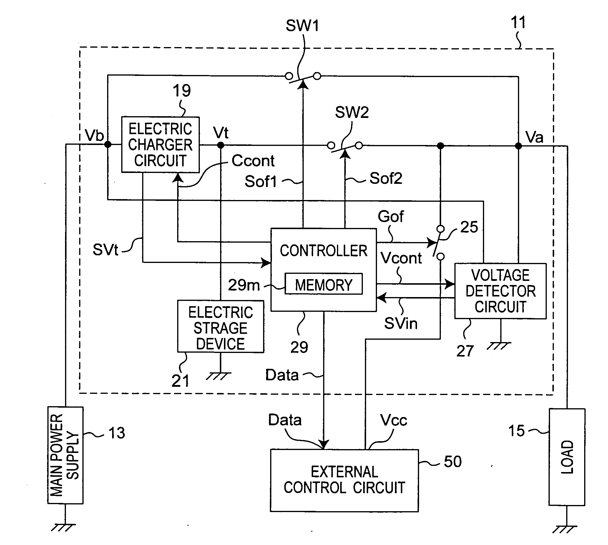
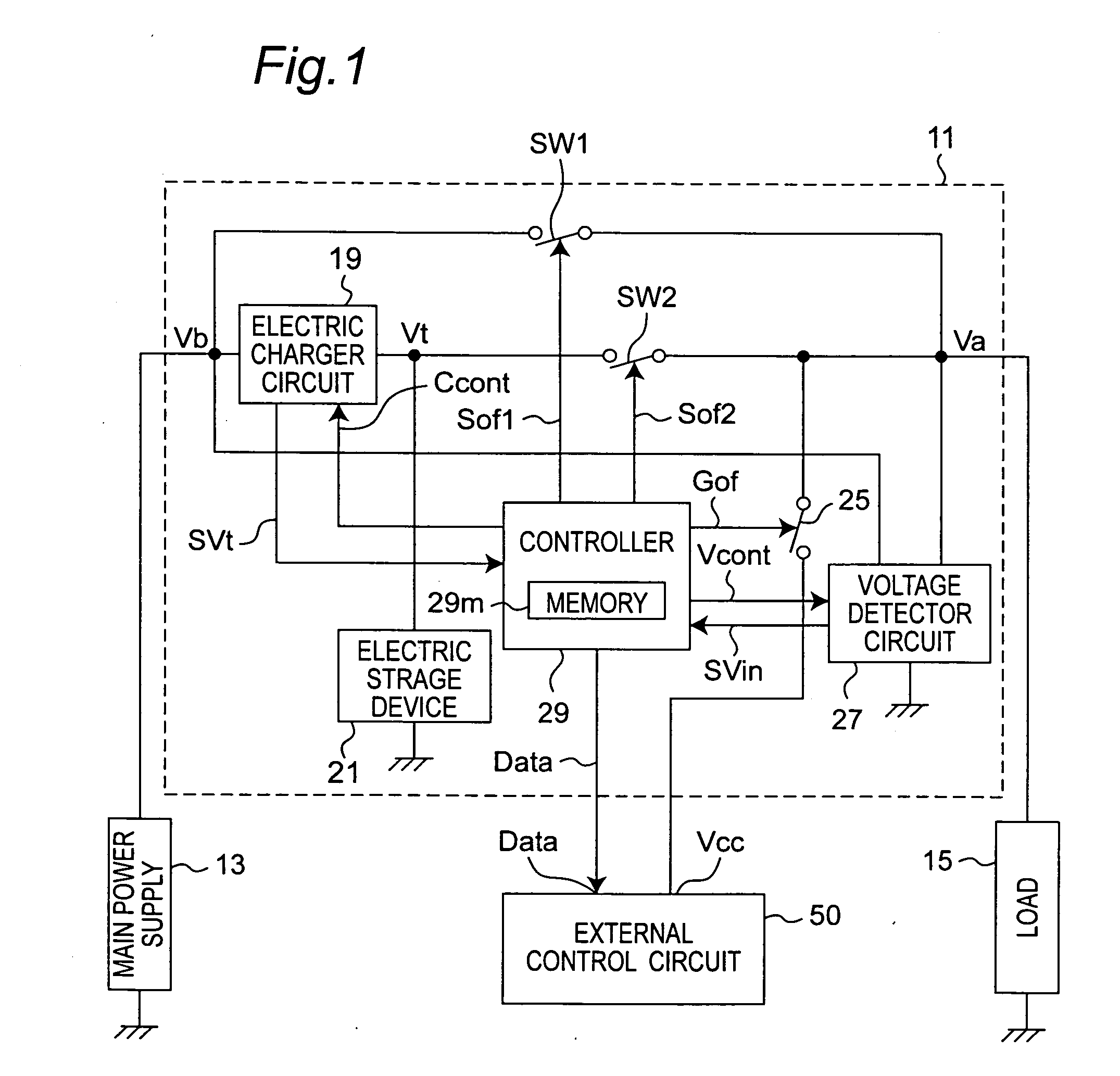
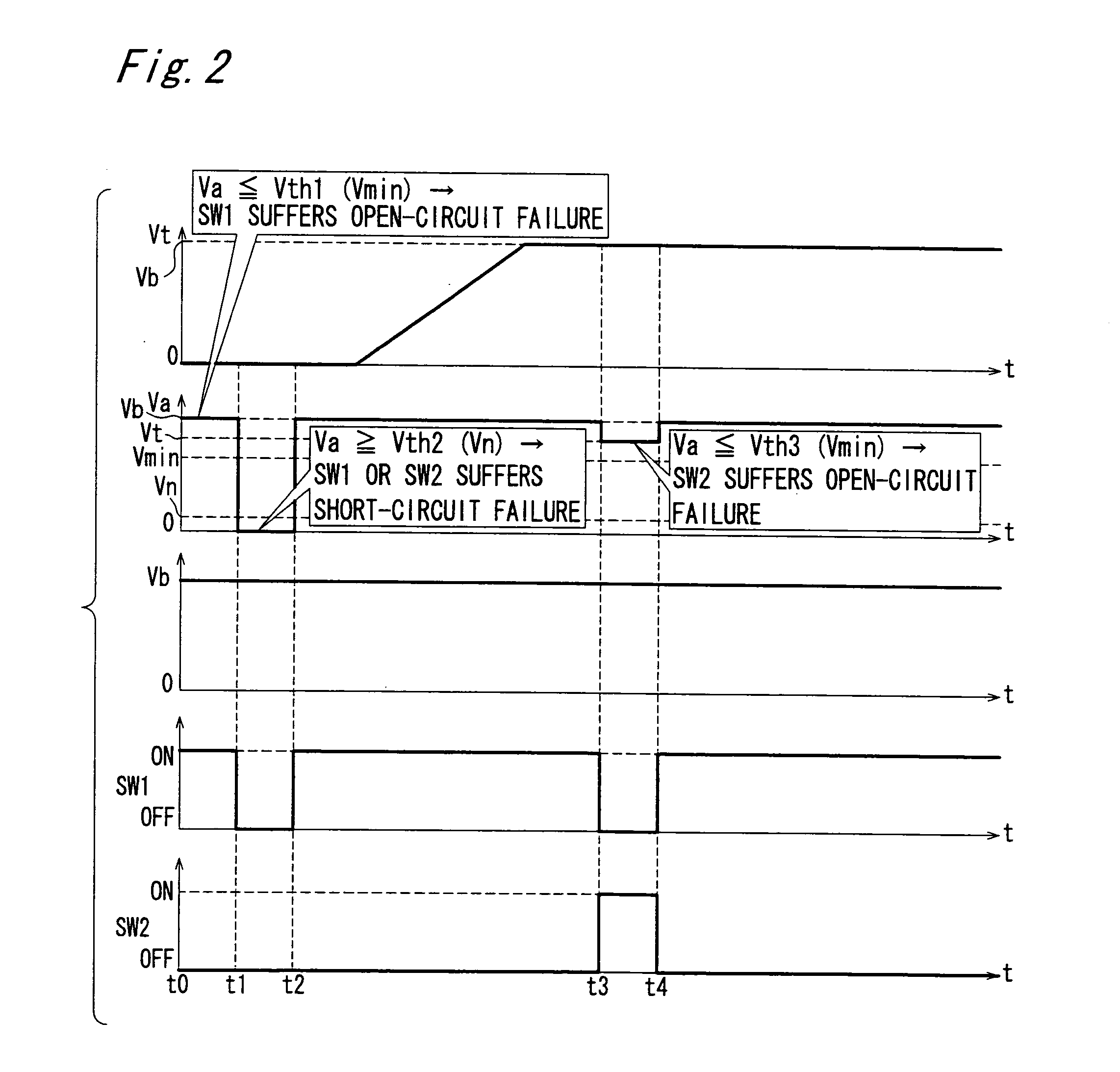
[0067]FIG. 1 is a block diagram of an electrical storage apparatus according to the first preferred embodiment of the present invention. FIG. 2 is a timing chart of respective voltages upon failure judgments of the electrical storage apparatus according to the first preferred embodiment of the present invention. In FIG. 1, the electrical storage apparatus 11 is connected between a main power supply 13 and a load 15. The main power supply 13 is a battery, and the load 15 is an audio device, a navigation device or the like.
[0068]The electrical storage apparatus 11 has the following configuration. First of all, a switch SW1 is connected between the main power supply 13 and the load 15. Therefore, when the switch SW1 is turned on, a power can be supplied directly from the main power supply 13 to the load 15 by bypassing the electrical storage circuit system. It is noted that, for example, a relay that has the smallest possible internal resistance value and is able to be externally contr...
second preferred embodiment
[0087]FIG. 3 is a block diagram of an electrical storage apparatus according to the second preferred embodiment of the present invention. FIG. 4 is a timing chart of respective voltages upon failure judgments of the electrical storage apparatus according to the second preferred embodiment of the present invention.
[0088]In the configuration of the second preferred embodiment in FIG. 3, components similar to those of the configuration of FIG. 1 are denoted by same reference numerals, and no description is provided therefor. That is, the features of the second preferred embodiment are as follows.
[0089](1) A first bypass FET FB1 and a second bypass FET FB2 are connected in series between the main power supply 13 and the load 15 in place of the switch SW1. It is noted that parasitic diodes 35a and 35b are formed in the bypass FETs FB1 and FB2, respectively.
[0090](2) A first main path FET FC1 and a second main path FET FC2 are connected in series between the electric storage device 21 and...
third preferred embodiment
[0107]FIG. 5 is a timing chart of respective voltages upon failure judgments of an electrical storage apparatus according to the third preferred embodiment of the present invention. Since the configuration of the electrical storage apparatus 11 according to the third preferred embodiment is the same as that of FIG. 3, no description is provided for the configuration, and a failure judgment method which is the features of the third preferred embodiment will be described.
[0108]The failure judgments of the first bypass FET FB1, the second bypass FET FB2, the first main path FET FC1 and the second main path FET FC2 can be made by the following combinations of conditions including the method of the second preferred embodiment. It is noted that the FETs which are not particularly described may be either on or off. Moreover, when plural conditions are described, any one of the conditions may be used.
[0109](1) When a judgment of the open-circuit failure of the first bypass FET FB1 is made:
[...
PUM
 Abstract
Description
Claims
Application Information