Radar level gauge system

a level gauge and radar technology, applied in the direction of using reradiation, radio wave reradiation/reflection, measurement devices, etc., can solve the problems of mechanical system robustness, accuracy and reliability, movable mechanical parts are likely to malfunction, etc., and achieve the effect of low cos

Inactive Publication Date: 2008-06-26
ROSEMOUNT TANK RADAR
View PDF10 Cites 19 Cited by
  • Summary
  • Abstract
  • Description
  • Claims
  • Application Information

AI Technical Summary

Benefits of technology

[0017]Still further, the measuring signals transmitted through the coaxial cable are preferably of a frequency below 3 GHz, and most preferably below 2 GHz, whereby it becomes possible to use conventional coaxial cables, which are commercially available to a relatively low cost.

Problems solved by technology

However, such mechanical systems are the subject of many problems.
For example, the environment in the tanks is often relatively rough, making the movable mechanical parts likely to malfunction over time.
Further, the floating member needs to be in contact with the fluid, which is disadvantageous since the surface is normally not still.
Accordingly, these mechanical system have problems with robustness, accuracy and reliability.
In spite of the above-discussed problems of the tape and float systems, there is often a reluctance to replace these systems with e.g. radar level gauging systems, since transition costs involved are relatively high.
Hereby, the wiring process becomes even more cumbersome and expensive.
Still further, the old float and tape systems often have fixed installations inside the tank and in the tank roof, which are difficult to replace, and which may prevent installation of a radar system.
The net result is that these transition costs often prevent upgrading of existing old float and tape systems.

Method used


Image

  • Radar level gauge system
  • Radar level gauge system
  • Radar level gauge system

Examples


Embodiment Construction

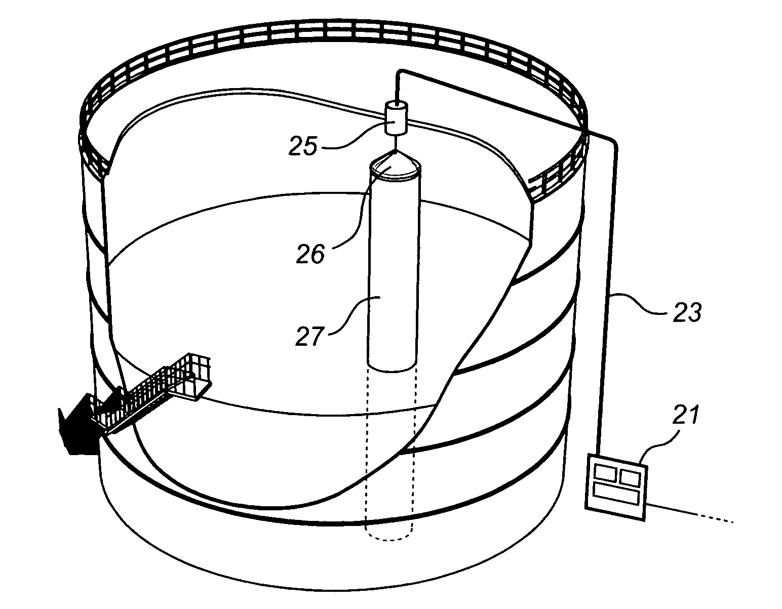
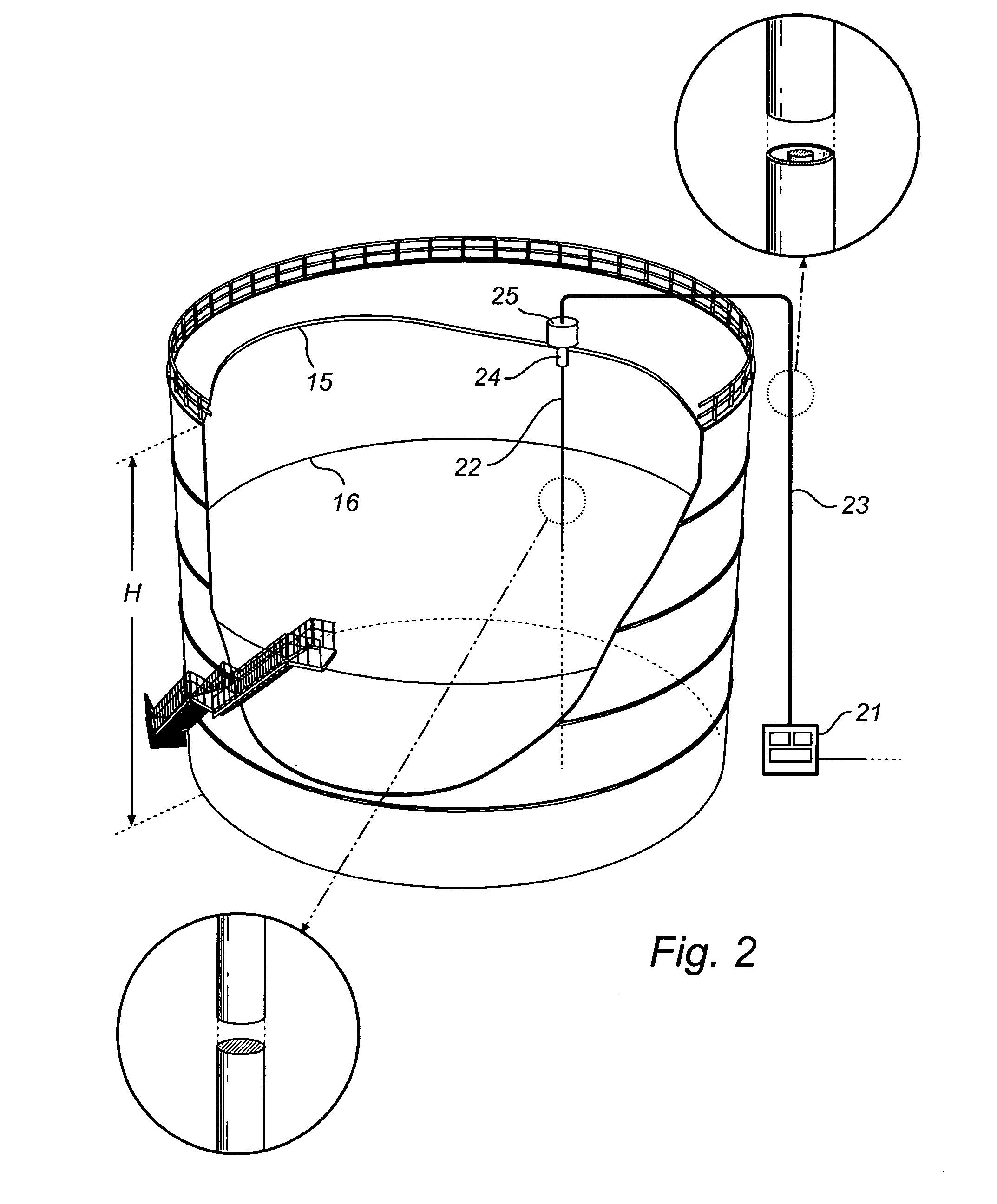
[0028]FIG. 2 shows schematically a radar level gauge system according to a first embodiment. In brief, the system in FIG. 2 comprises a signaling unit 21 for transmitting and receiving radar signals and processing the received signals in order to determine the level 16 of a filling material in the tank 15. The signaling unit 21 is arranged outside the tank, and preferably close to the ground level. This position typically corresponds to the location of the housing 12 of a mechanical system, as discussed with reference to FIG. 1. A wave guide 22 is arranged within the tank, and extending vertically between the tank roof and the bottom. The tank is of a height H between the base and the roof of the tank.

[0029]The signaling unit 21 houses a transmitter for transmitting measuring signals towards the surface of the filling material in said wave guide and a receiver for receiving echo signals from the tank, as is per se known in the art. Further, the transmitter is preferably arranged to ...


PUM


Abstract

A radar level gauge system for determining a filling level of a filling material in a tank is disclosed. The system comprises: a wave guide arranged within the tank; a signaling unit arranged outside the tank, and comprising a transmitter for transmitting measuring signals towards the surface of the filling material in said wave guide and a receiver for receiving echo signals from the tank, wherein the transmitter is preferably arranged to provide measuring signals of a frequency below 3 GHz. Further, a coaxial cable for forwarding the measuring signals and the echo signals between the wave guide and the signaling unit is provided, wherein the coaxial cable is of a length which is at least as long as the height of the tank. By means of this radar level gauge system, it becomes relatively easy and inexpensive to replace mechanical level gauge systems, so-called “float and tape systems”.

Description

FIELD OF THE INVENTION [0001]The present invention relates to a radar level gauging system for determining a filling level of a filling material in a tank, and in particular a radar level gauge system that can be used for replacing existing old mechanical level gauging systems of the so-called float and tape type.BACKGROUND OF THE INVENTION [0002]For at least a hundred years, mechanical systems have been used for determining filling levels in tanks housing e.g. liquids, such as in petroleum storage tanks, grain containers and containers for housing volatile liquids. Such known mechanical systems, commonly referred to as “float and tape systems” are e.g. disclosed in U.S. Pat. No. 2,904,998, 3,057,199, 3,148,542 and 4,459,584. Even though other alternative level gauging techniques have since been developed, such as radar level gauging, the old float and tape systems are still commonly used.[0003]A typical float and tape system, as is illustrated in FIG. 1,basically consists of a meta...

Claims


Application Information

Patent Timeline
Patent Type & Authority Applications(United States)
IPC IPC(8): G01S13/00
CPCG01F23/284
Inventor JIRSKOG, ANDERSDRAGEN, PETER
Owner ROSEMOUNT TANK RADAR
Why Eureka
Try Eureka