
Color passive matrix bistable liquid crystal display system and method for driving the same

Active Publication Date: 2008-06-26
IND TECH RES INST
View PDF6 Cites 23 Cited by
  • Summary
  • Abstract
  • Description
  • Claims
  • Application Information

AI Technical Summary

Benefits of technology

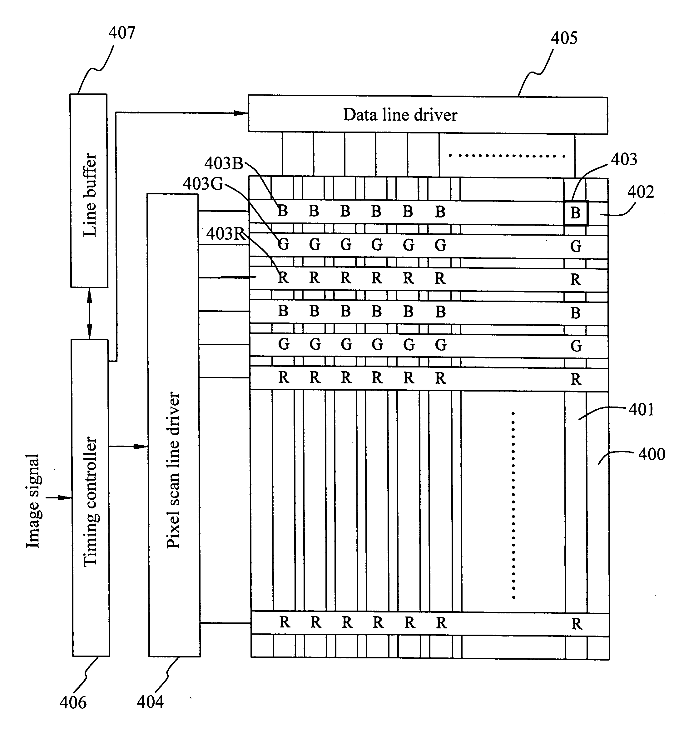
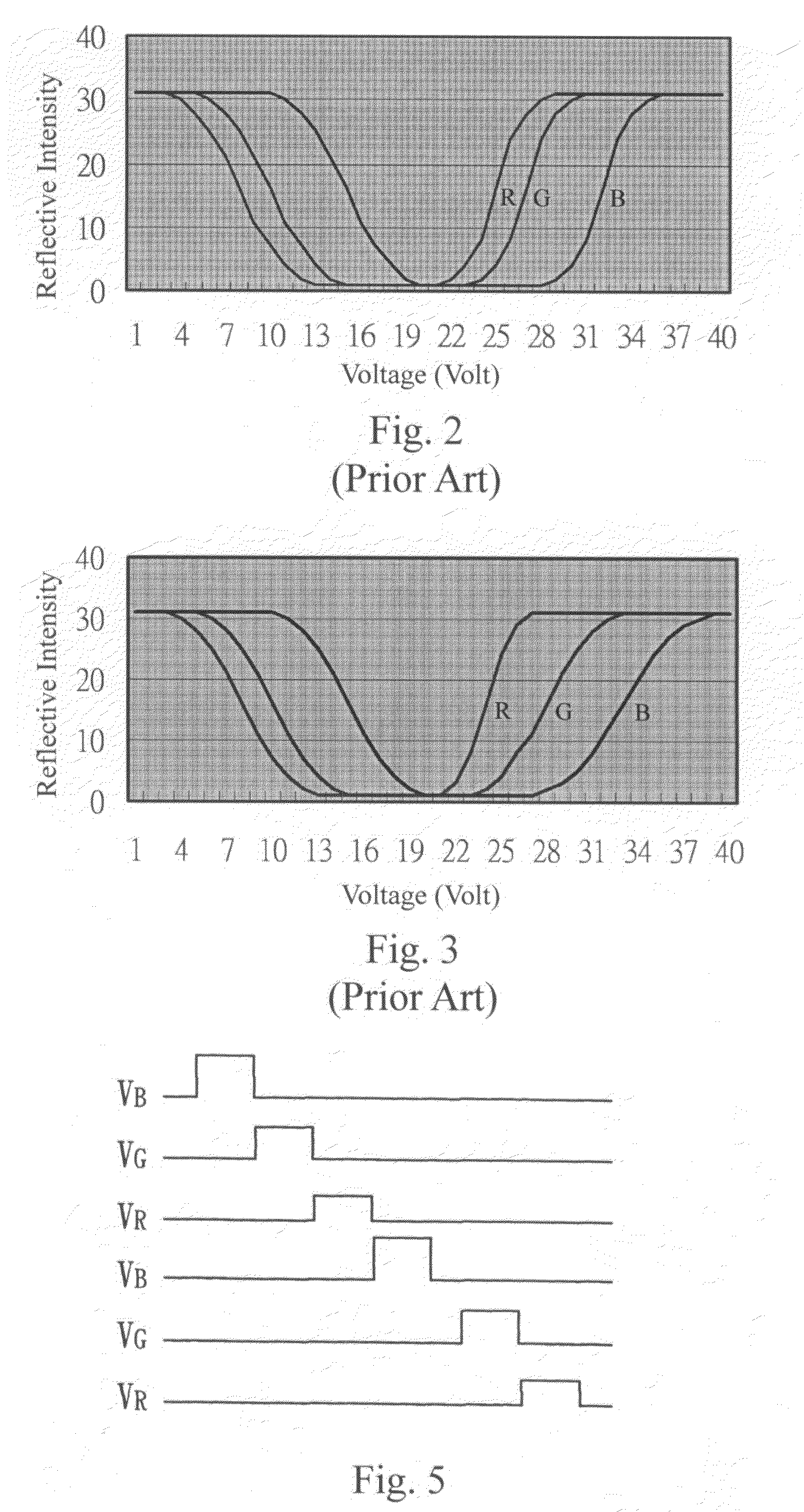
[0010]Additionally, the data electrodes of the present color passive matrix bistable liquid crystal display system can be switched to the respective voltage levels corresponding to the sub-pixels of different colors when the scan lines are scanned so as to satisfy the situation that the voltage levels of the data electrodes for the sub-pixels of different colors are different. And thus, it is not necessary to develop additional addressing data driving circuit for providing respective addressing voltages to the sub-pixels of different colors.
[0011]By way of the arrangement of the sub-pixels, the present color passive matrix bistable liquid crystal display system can satisfy the demand that the respective scan driving voltage levels and the respective data voltage levels corresponding to the sub-pixels of different colors are different without increasing the complexity of the circuit design of the driving system. The image quality is improved.

Problems solved by technology

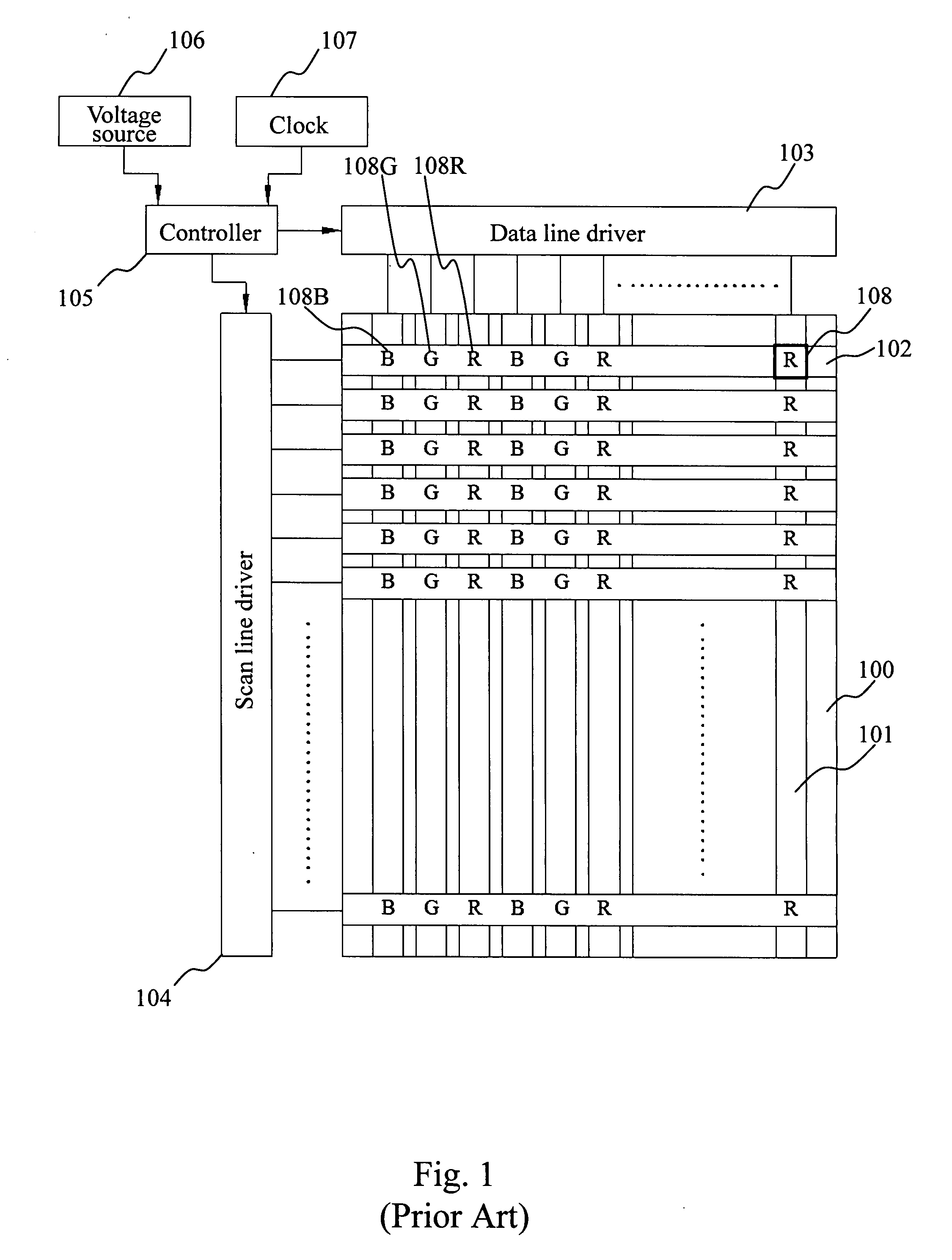
As such, the pixel arrangement and driving method of the conventional color passive matrix bistable liquid crystal display device can not meet the demand that the liquid crystal cells of different illuminating colors have different scan driving voltages.
It is necessary to develop additional addressing circuits to provide respective addressing voltages to the liquid crystals of different illuminating colors, and that makes the circuit design of the data line driver 103 become more complicated.

Method used


Image

  • Color passive matrix bistable liquid crystal display system and method for driving the same
  • Color passive matrix bistable liquid crystal display system and method for driving the same
  • Color passive matrix bistable liquid crystal display system and method for driving the same

Examples


Embodiment Construction

[0017]The present invention provides a color passive matrix bistable liquid crystal display system, which provides respective scan driving voltages to the scan electrodes in accordance with the illuminating colors of the sub-pixels corresponding thereto for driving the liquid crystals such that the demand that the sub-pixels of different colors require different scan driving voltages is satisfied. In other words, the present invention provides an appropriate arrangement of the liquid crystals of different illuminating colors to meet the need of the color passive matrix bistable liquid crystal display device and a driving system suitable for the same. In the present invention, the liquid crystals of different illuminating colors are aligned in the directions perpendicular to the scan electrodes and the liquid crystals of same illuminating colors are aligned in the directions parallel to the scan electrodes. Moreover, the present system provides a line buffer for resorting the pixel d...


PUM


Abstract

This invention provides a color passive matrix bistable liquid crystal display system, in which one respective scan line corresponds to sub-pixels of same color and neighboring scan lines correspond to sub-pixels of different colors. The scan lines are grouped in accordance with the colors of the sub-pixels corresponding thereto such that different scan driving voltages can be provided to the sub-pixels of different colors when the scan lines are scanned. By way of the arrangement of the sub-pixels, different scan driving voltages are switched to the respective scan lines in accordance with the colors of the sub-pixels corresponding thereto. As a result, a demand that the sub-pixels of different colors require different scan driving voltages is satisfied. The image quality is improved.

Description

BACKGROUND OF THE INVENTION[0001]1. Field of the Invention[0002]The present invention relates to a passive matrix bistable liquid crystal display system, and more particularly to a color passive matrix bistable liquid crystal display system and a method for driving the same.[0003]2. Description of the Related Art[0004]FIG. 1 is a schematic block diagram of the conventional color passive matrix bistable liquid crystal display device, which includes a lower substrate 100, a plurality of data electrodes 101 aligned in parallel, a plurality of scan electrodes 102 aligned in parallel, a data line driver 103, a scan line driver 104, a controller 102, a voltage source 106, a clock 107 and a plurality of blue light bistable liquid crystal cells (B) 108B, a plurality of green light bistable liquid crystal cells (G) 108G and a plurality of red light bistable liquid crystal cells (R) 108R. The data electrodes 101 are disposed on one surface of the lower substrate 100, and the scan electrodes 1...

Claims


Application Information

Patent Timeline
IPC IPC(8): G09G3/36
CPCG09G3/364G09G2320/0242G09G2300/0452G09G3/3681
Inventor CHEN, CHIH-JENLU, CHIH-CHIANGCHEN, TAI-ANNCHANG, CHUNG-YI
Owner IND TECH RES INST
Learn More