[0006]Accordingly, it is an object of the present invention to create a linear roller bearing element of the type described in the
preamble, which enables the rolling elements to circulate smoothly without being subjected to greater loads, with a minimum of
noise, using simple means.
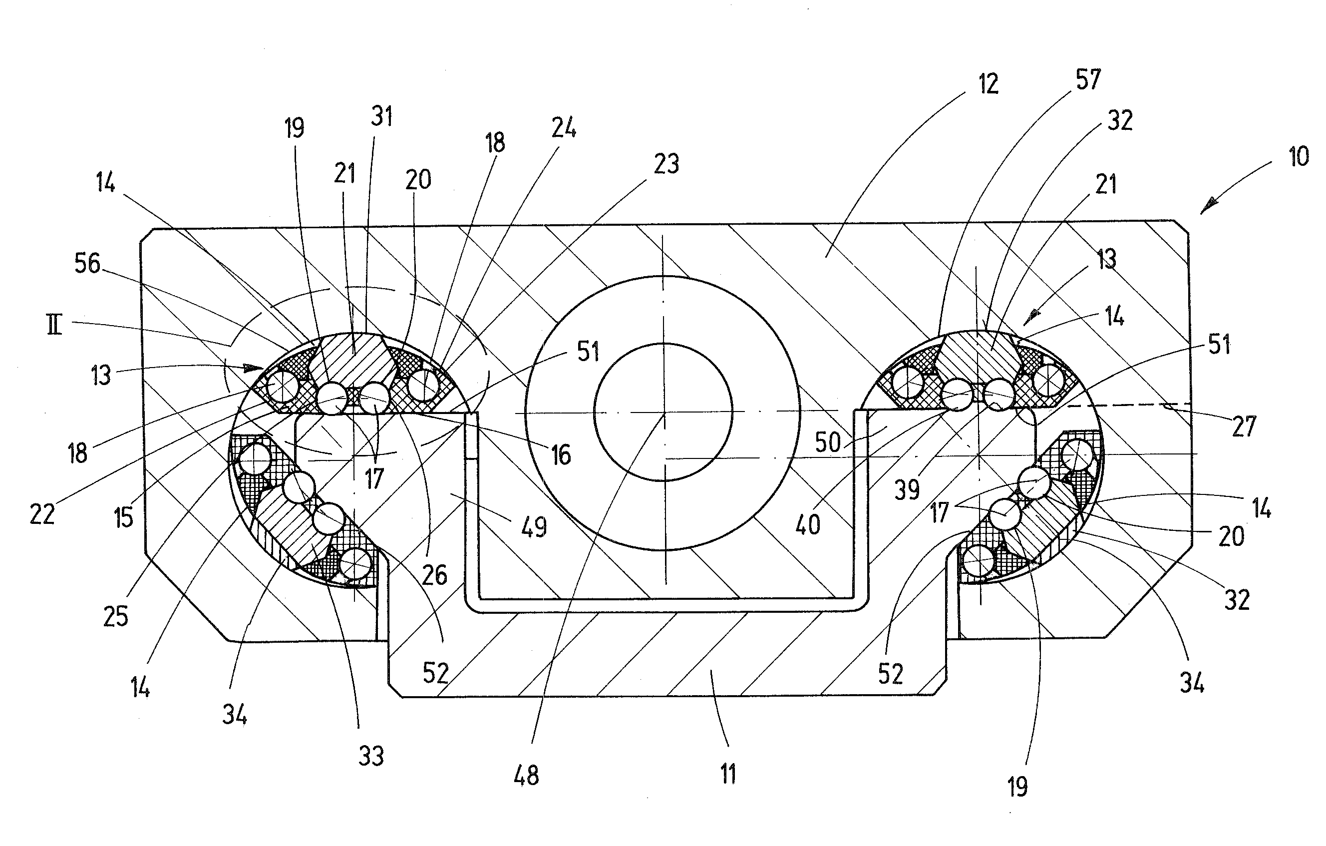
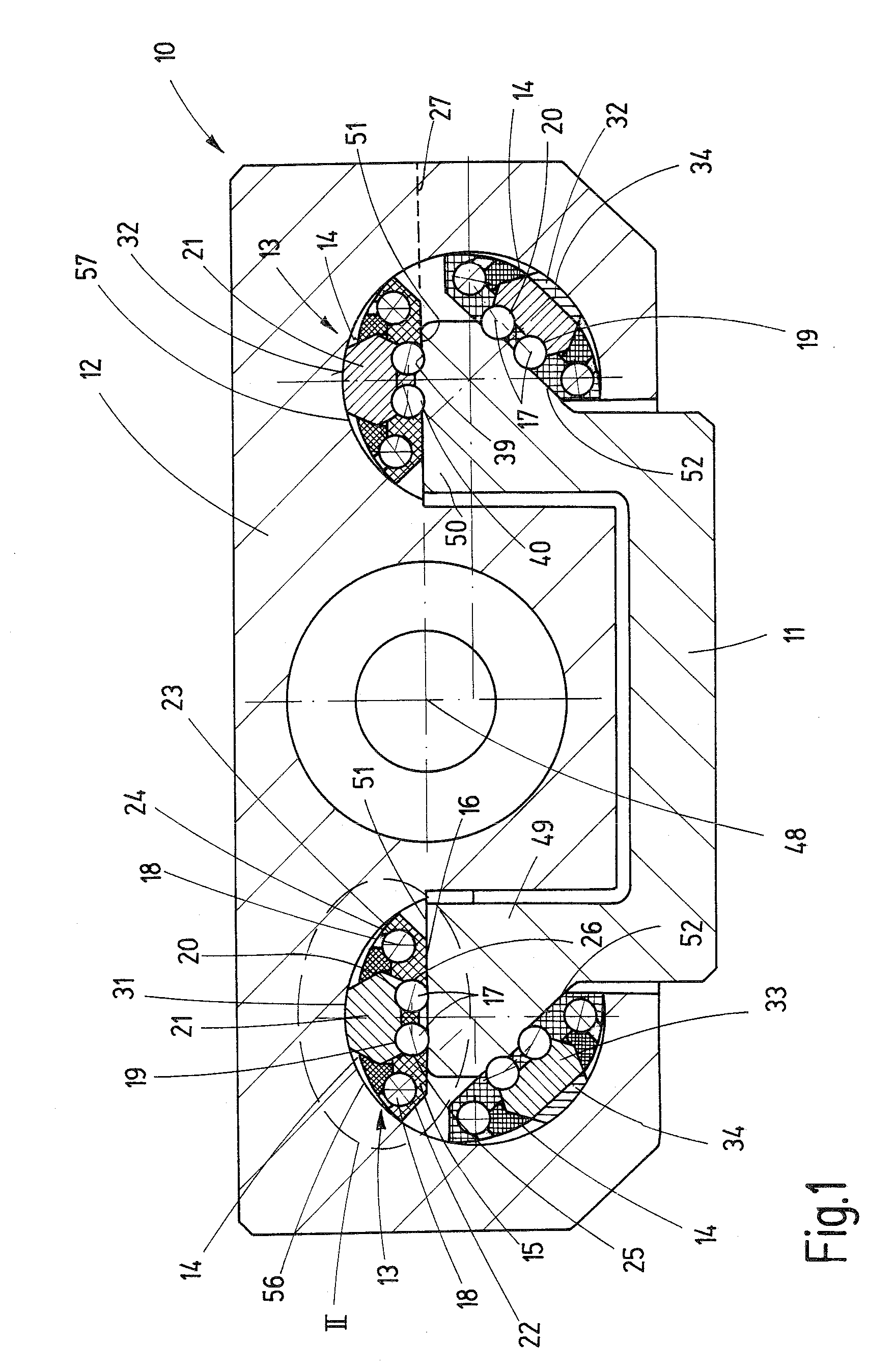
[0008]As a result, individual, independent and ready-to-install raceway elements are created, with which the individual raceways remain in a fixed, permanent relation to each other. The raceway elements include the carrier raceway, return, and turnaround, including the rolling elements. Due to this fixed, permanent relationship, there is no risk that, e.g., the return channels may become displaced relative to the carrier raceways of the carrier body.
[0009]The roller bearing element operates quietly, with low wear and the associated long service life, is small and compact, and requires very little installation space when installed in a linear roller bearing guide. In this state, due to the single-axis or biaxial, convex or concave curvature on the back side of the carrier body, the roller bearing element enables the carrier body to automatically adapt to the course of the raceways of the guide rail, and to distribute the load on the individual rolling elements as evenly as possible. As a result, essentially the same load is applied in each row, in every load state.
[0010]Furthermore, since the particular return channels are located on the side, the carrier body may be designed small and compact in terms of its cross-sectional expansion, since its support cross section need not be reduced by return channels that would extend in the region of the carrier body. The same applies for the support region of the guide carriage, on which the carrier body rests. This support cross section does not need to be reduced in size and therefore weakened, either, as a result of the location of the return channels. It is advantageous that the support of the raceway elements therefore takes place via the back of the carrier body in a
solid region of the guide carriage. The stiffness of a roller bearing guide is increased as a result. The manufacturing costs are also reduced. It is also advantageous that the raceway elements are acted upon with a
spring force acting in the direction of the guide rail. As a result, even when play should arise on one side when force is applied, therefore resulting in displacement, the particular raceway element is still pressed with the rolling elements against the guide rail thereby ensuring constant contact between the rolling elements and the related guide surfaces and preventing flat spots from forming on the rolling elements.
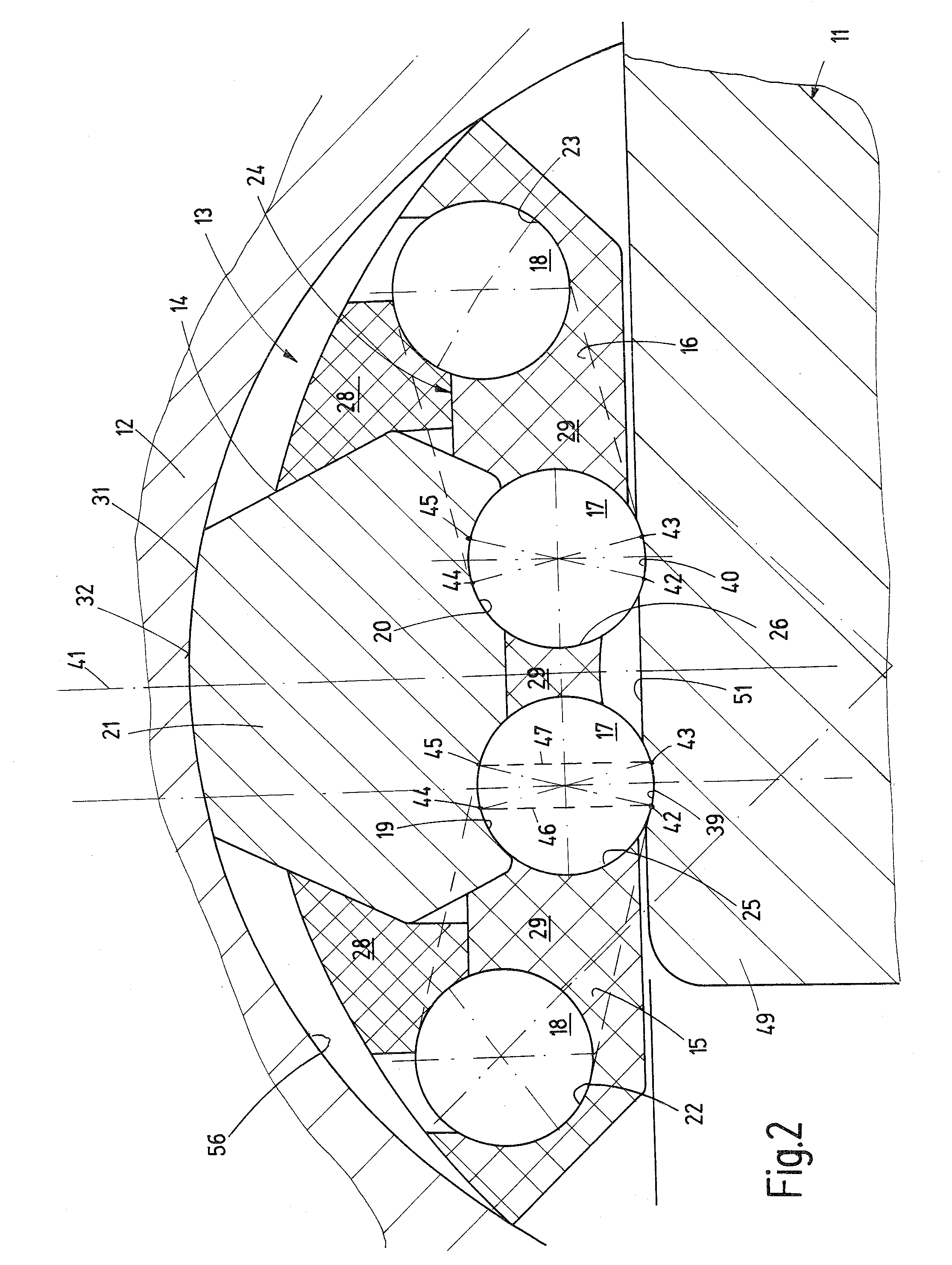
[0011]This is advantageous with highly dynamic drives in particular, since all
load bearing rolling elements are accelerated by the contact with the guide raceways. This results in a roller bearing circulation without slip. This makes it possible to design the raceways for the rolling elements as a four-
point contact bearing with a small
contact angle. In this manner, the load-
bearing capacity of the rolling element contact may be nearly doubled. This results in linear roller bearing guides with extremely
high load-bearing capacities.

