Process cartridge, electrophotographic image forming apparatus, and electrophotographic photosensitive drum unit

a technology of drum unit, which is applied in the direction of electrographic process apparatus, optics, instruments, etc., can solve the problems of difficult to prevent non-uniform rotation of the photosensitive drum, and the operation of the electrophotographic image forming apparatus

Active Publication Date: 2008-06-26
CANON KK
View PDF101 Cites 444 Cited by
  • Summary
  • Abstract
  • Description
  • Claims
  • Application Information

AI Technical Summary

Benefits of technology

[0013]A principal object of the present invention is to provide a process cartridge, a photosensitive drum unit used in the process cartridge, and an electrophotographi

Problems solved by technology

As a result, operability of the maintenance of the electrophotographic image forming apparatus.
However, in this constitution a driving connection portion between

Method used


Image

  • Process cartridge, electrophotographic image forming apparatus, and electrophotographic photosensitive drum unit
  • Process cartridge, electrophotographic image forming apparatus, and electrophotographic photosensitive drum unit
  • Process cartridge, electrophotographic image forming apparatus, and electrophotographic photosensitive drum unit

Examples


embodiment 1

(1) Brief Description of Process Cartridge

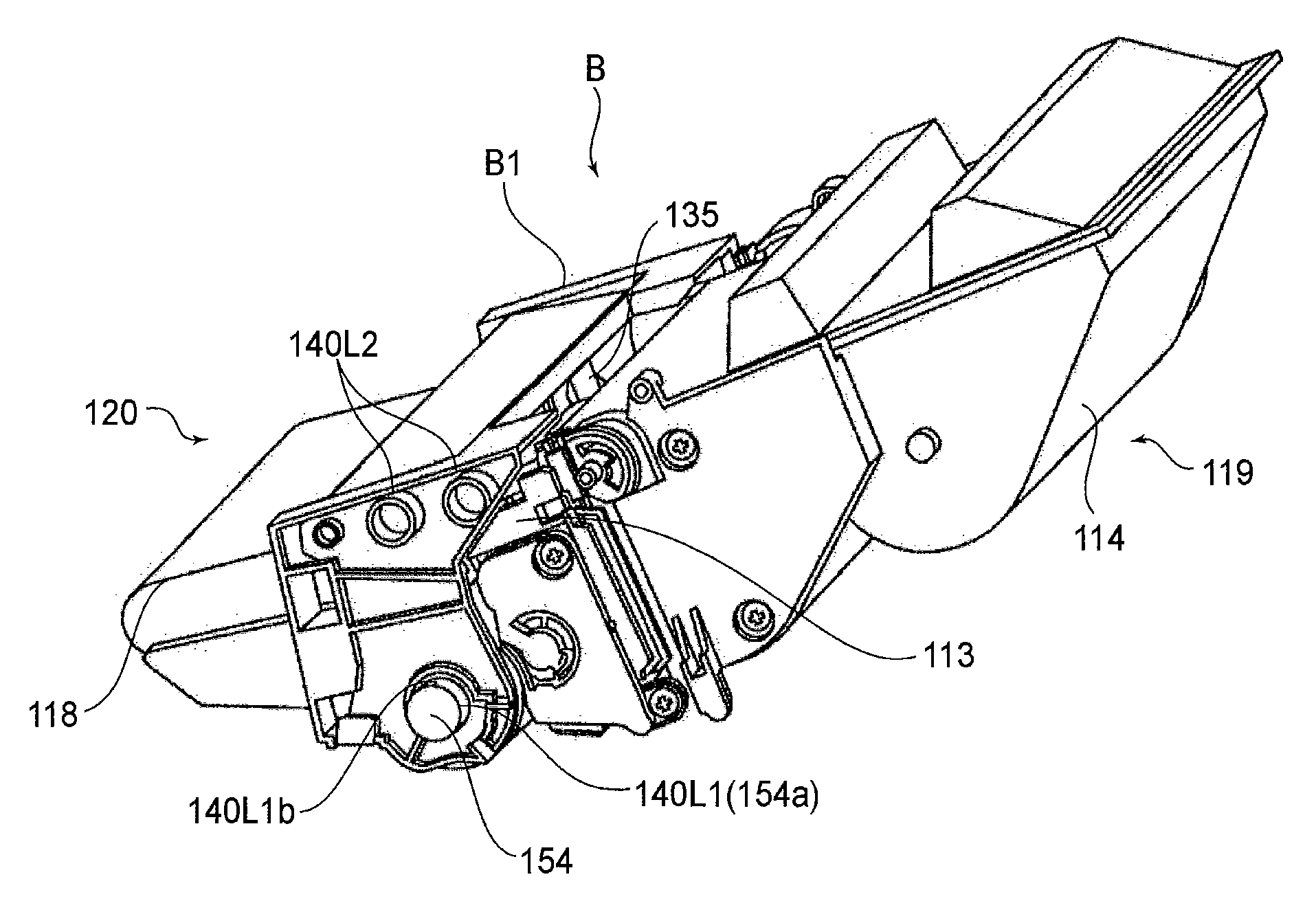
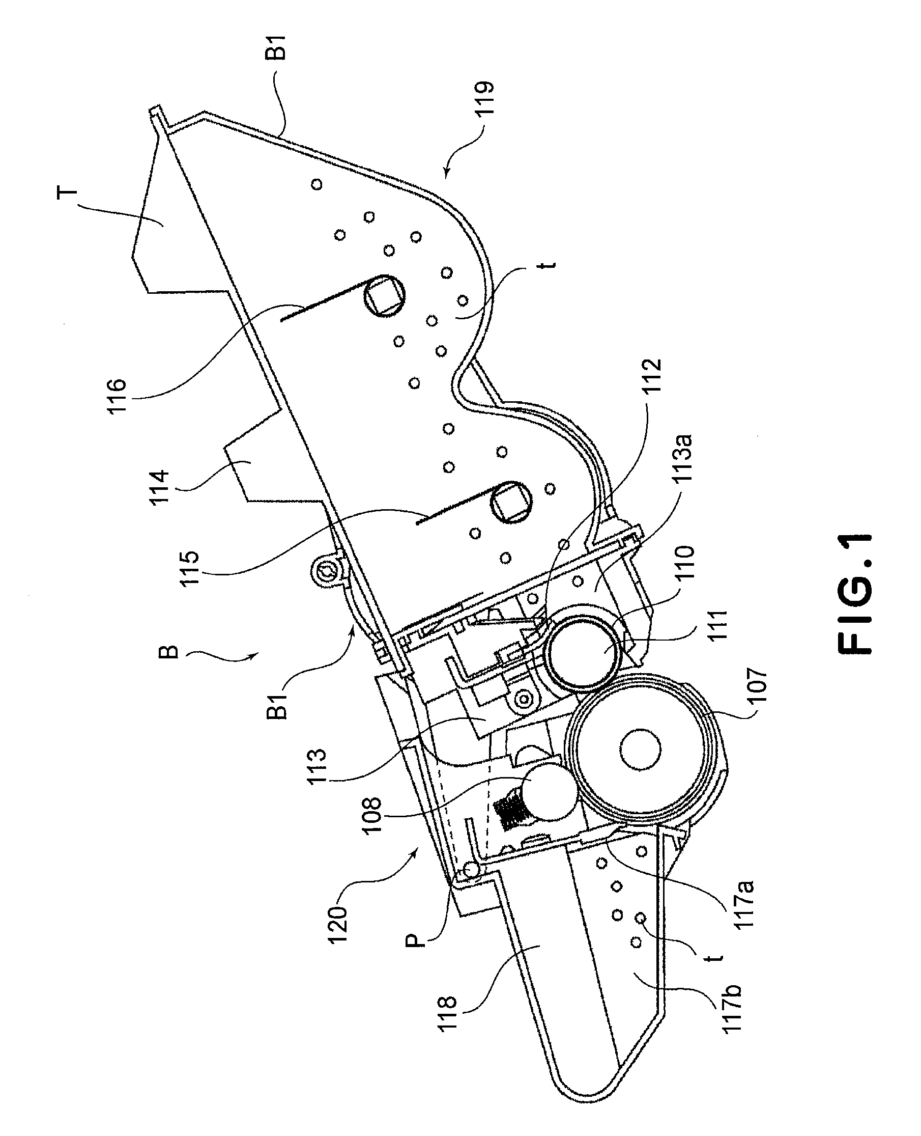
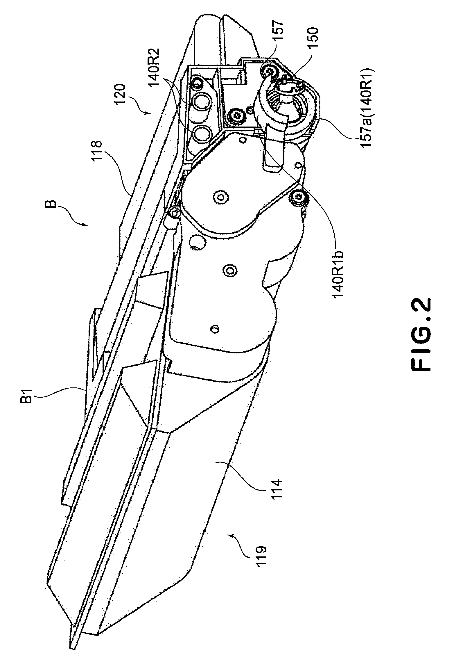
[0145]A process cartridge B to which an embodiment of the present invention is applied will be described with reference to FIGS. 1 to 4. FIG. 1 is a sectional view of the cartridge B. FIGS. 2 and 3 are perspective views of the cartridge B. FIG. 4 is a sectional view of an electrophotographic image forming apparatus main assembly A (hereinafter referred to as an “apparatus main assembly A”). The apparatus main assembly A corresponds to a portion of the electrophotographic image forming apparatus from which the cartridge B is excluded.

[0146]Referring to FIGS. 1 to 3, the cartridge B includes an electrophotographic photosensitive drum 107. The photosensitive drum 107 is rotated by receiving a rotational force from the apparatus main assembly A by a coupling mechanism when the cartridge B is mounted in the apparatus main assembly A as shown in FIG. 4. The cartridge B is mountable to and demountable from the apparatus main assembly A by a user.

[0...

embodiment 2

[0336]Referring to FIG. 35-FIG. 40, the second embodiment to which applied the present invention will be described.

[0337]In the description of this embodiment, the same reference numerals as in Embodiment 1 are assigned to the elements having the corresponding functions in this embodiment, and the detailed description thereof is omitted for simplicity. This applies also about the other embodiment described in the below.

[0338]The this embodiment is effective not only for the case of the mounting and the dismounting of the cartridge (B) relative to the apparatus main assembly (A) but also the case of the dismounting only of the cartridge (B) from the apparatus main assembly (A).

[0339]More particularly, when the drive shaft 180 stops, the drive shaft 180 is stopped with the predetermined phase by the control of the apparatus main assembly (A) in other words, it stops so that the pin 182 may become at a predetermined position. Moreover, the phase of the coupling 14150 (150) is set in al...

embodiment 3

[0358]Referring to FIG. 41-FIG. 45, a third embodiment will be described.

[0359]FIG. 41 is a sectional view which illustrates a state where a door of an apparatus main assembly A is open. FIG. 42 is a perspective view which illustrates a mounting guide. FIG. 43 is the enlarged view of a driving side surface of the cartridge. FIG. 44 is a perspective view, as seen from a driving side, of the cartridge. FIG. 45 shows a view which illustrates a state of inserting the cartridge into an apparatus main assembly.

[0360]In this embodiment, for example, as in the case of the clamshell type image forming device, the cartridge is mounted downwardly. A typical clamshell type image forming apparatus is shown in FIG. 41. The apparatus main assembly A2 comprises a lower casing D2 and an upper casing E2. And, the upper casing E2 is provided with a door 2109 and an inside exposure device 2101 of the door 2109. Therefore, when the upper casing E2 is opened upward, the exposure device 2101 retracts. And...


PUM


Abstract

A process cartridge for use with a main assembly of an electrophotographic image forming apparatus, the main assembly including a driving shaft, to be driven by a motor, having a rotational force applying portion, wherein the process cartridge is dismountable from the main assembly in a direction substantially perpendicular to an axial direction of the driving shaft, the process cartridge includes i) an electrophotographic photosensitive drum having a photosensitive layer at a peripheral surface thereof, the electrophotographic photosensitive drum being rotatable about an axis thereof; ii) process means actable on the electrophotographic photosensitive drum; iii) a coupling member engageable with the rotational force applying portion to receive a rotational force for rotating the electrophotographic photosensitive drum, the coupling member being capable of taking a rotational force transmitting angular position for transmitting the rotational force for rotating the electrophotographic photosensitive drum to the electrophotographic photosensitive drum and a disengaging angular position in which the coupling member is inclined away from the axis of the electrophotographic photosensitive drum from the rotational force transmitting angular position, wherein when the process cartridge is dismounted from the main assembly of the electrophotographic image forming apparatus in a direction substantially perpendicular to the axis of the electrophotographic photosensitive drum, the coupling member moves from the rotational force transmitting angular position to the disengaging angular position.

Description

FIELD OF THE INVENTION AND RELATED ART[0001]The present invention relates to a process cartridge, an electrophotographic image forming apparatus to which the process cartridge is detachably mountable, and an electrophotographic photosensitive drum unit.[0002]Examples of the electrophotographic image forming apparatus include an electrophotographic copying machine, an electrophotographic printer (a laser beam printer, an LED printer, and so on), and the like.[0003]The process cartridge is prepared by integrally assembling an electrophotographic photosensitive member and process means acting on the electrophotographic photosensitive member into a unit (cartridge) and is mounted to and demounted from a main assembly of the electrophotographic image forming apparatus. For example, the process cartridge is prepared by integrally assembling the electrophotographic photosensitive member and at least one of a developing means, a charging means, and a cleaning means as the process means into...

Claims


Application Information

Patent Timeline
IPC IPC(8): G03G15/00
CPCG03G15/757G03G2221/1657G03G21/186G03G21/1853G03G21/1803G03G15/00G03G21/1821G03G21/1842G03G21/185G03G21/1857G03G21/1647G03G15/751G03G21/1817G03G21/1814
Inventor UENO, TAKAHITOMIYABE, SHIGEOMORIOKA, MASANARIHISANO, MASATO
Owner CANON KK
Why Eureka
Try Eureka