
Contact, and card adaptor and card connector having the same

Inactive Publication Date: 2008-06-26
HOSIDEN CORP
View PDF13 Cites 5 Cited by
  • Summary
  • Abstract
  • Description
  • Claims
  • Application Information

AI Technical Summary

Benefits of technology

[0011]In order to solve the problem, the contact of the invention is a contact which is to be placed in a card insertion space and contacted with a contact pad which is disposed on one principal face of a card, wherein a first plate spring piece portion having a first fulcrum portion in one side extends in a cantilevered manner from the first fulcrum portion in a direction opposite to a card insertion direction so as to be elastically deformable in a thickness direction of the card, a second plate spring piece portion having in one side a second fulcrum portion which is another side of the first plate spring piece portion is formed in a shape where the second plate spring piece portion extends at an inclination angle in a cantilevered manner from the second fulcrum portion in the card insertion direction so as to be elastically deformable in the card thickness direction, and another side of the second plate spring piece portion is to be contacted with the contact pad of the card. The plate spring piece portion (second plate spring piece portion) which is to be contacted with the contact pad of the card is configured as the unopposed type in which the portion extends at an inclination angle in a cantilevered manner from the fulcrum portion (second fulcrum portion) in the card insertion direction (forward direction). Therefore, the possibility that buckling is caused by card insertion can be eliminated, and the contact pressure can be increased or decreased in accordance with increase or decrease of a displacement amount of the contact. Consequently, a sufficient contact pressure can be ensured even when the spring constant of the contact is not increased, the range of a displacement amount where an adequate contact pressure can be obtained is not narrowed, and it is not required to strictly manage the position of a contacting portion to suppress dispersions. As a result, a stable contact pressure of the contact can be easily ensured. Structurally, a stress can be dispersed to two portions (the first fulcrum portion of the first plate spring piece portion and the second fulcrum portion of the second plate spring piece portion), and in addition a generated stress can be suppressed to a low level by not increasing the spring constant. This stress relaxation can prolong the life period of the contact. Therefore, a long life period of the contact can be easily ensured.
[0012]In the contact of the invention, the second plate spring piece portion may be formed in a shape where it is folded back from the other side of the first plate spring piece portion, or preferably the second plate spring piece portion may be formed by partly cutting and raising the first plate spring piece portion. In this configuration, the second plate spring piece portion can directly extend at an inclination angle in a cantilevered manner from the other side of the first plate spring piece portion in the card insertion direction (forward direction), without passing through a folded back portion (radius of curvature). Therefore, a larger displacement amount of the contact can be obtained, and a stable contact pressure of the contact can be ensured more easily. Preferably, an attaching portion to a case member for forming a card insertion space may be continuously integrated with the first fulcrum portion of the first plate spring piece portion. Preferably, an external connection terminal may be continuously integrated with the attaching portion.
[0013]The card adaptor of the invention comprises the above-described contact of the invention, and the case member for forming the card insertion space constitutes an adaptor body having an external shape for another card which is larger than the card that is to be inserted into the card insertion space. Therefore, a stable contact pressure and a long life period can be easily ensured in the contact for card contact disposed in the card adaptor.
[0014]The card connector of the invention comprises the above-described contact of the invention, and the case member for forming the card insertion space constitutes a connector housing having a box-like shape configured by an insulative lower case to which the contact is attached, and a conductive upper case which is coveringly attached to the lower case. Therefore, a stable contact pressure and a long life period can be easily ensured in the contact for card contact disposed in the card connector.

Problems solved by technology

Accordingly, it is difficult to ensure a sufficient contact pressure (a contact pressure is proportional to a contact displacement amount in accordance with Hook's law).
There is the possibility that buckling is caused by card insertion.
Therefore, a stable contact pressure cannot be obtained unless the position of a contacting portion is strictly managed to suppress dispersions, and it is difficult to ensure a stable contact pressure.

Method used


Image

  • Contact, and card adaptor and card connector having the same
  • Contact, and card adaptor and card connector having the same
  • Contact, and card adaptor and card connector having the same

Examples


Embodiment Construction

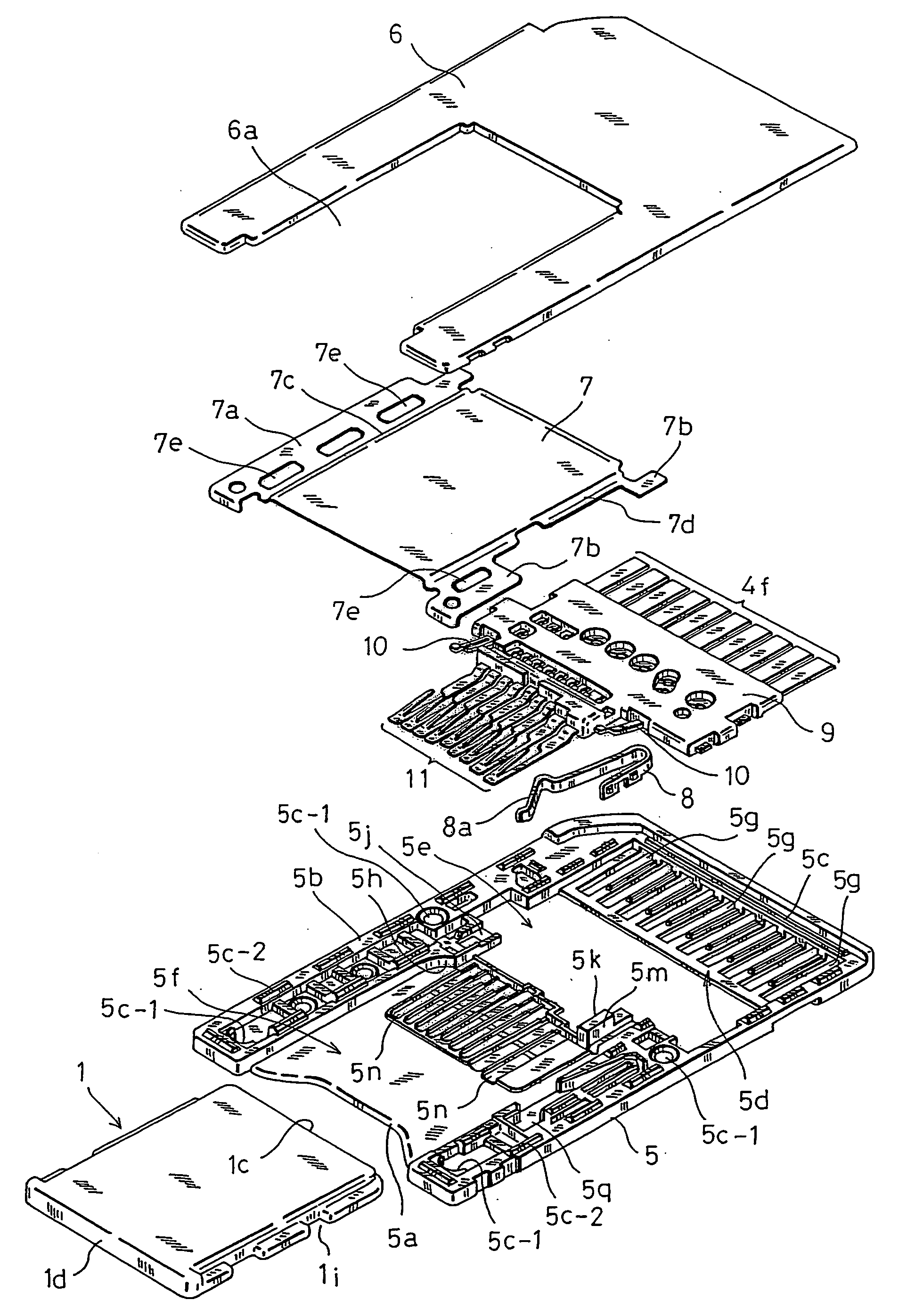
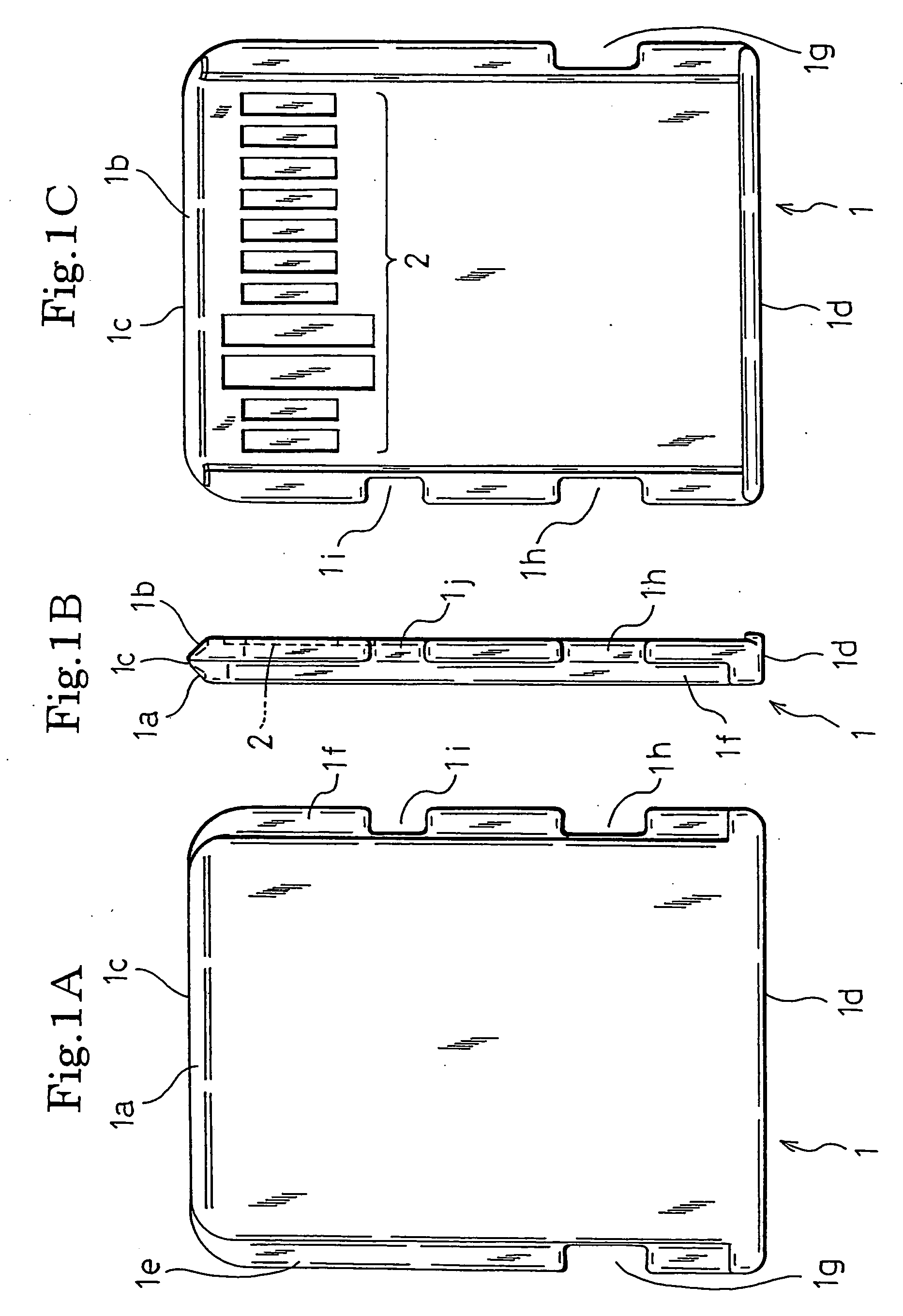
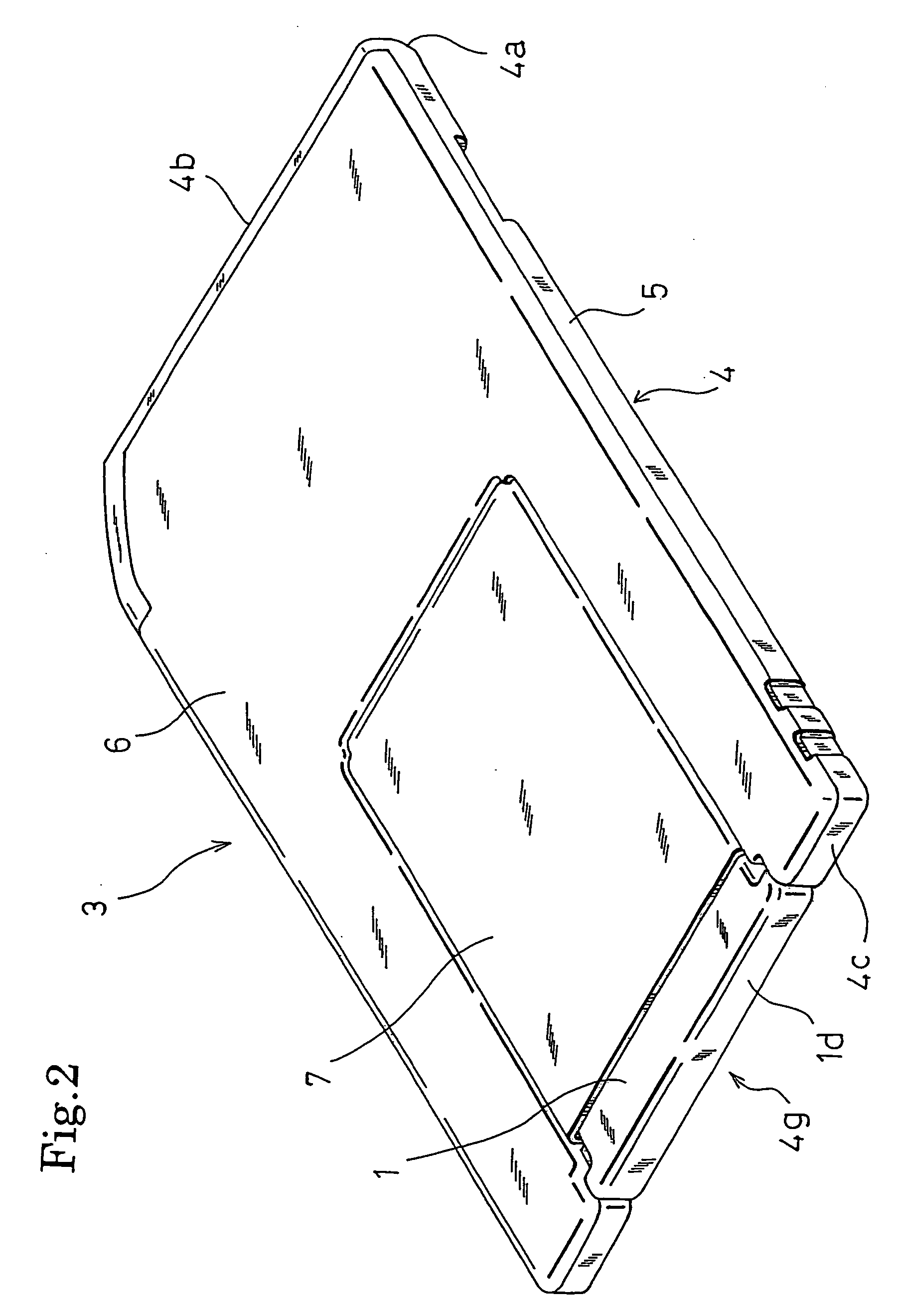
[0033]Hereinafter, an embodiment of the connector and card adaptor having it according to the invention will be described with reference to FIGS. 1 to 12. The embodiment is a card adaptor for connecting a memory card according to a certain standard in which size reduction is not specified, for example, Memory Stick PRO Duo (a trademark of Sony Corporation) (hereinafter, referred to as “large card”), to a card connector corresponding to another memory card according to another standard in which the size is more reduced than the certain standard, for example, Memory Stick Micro (a trademark of Sony Corporation) (hereinafter, referred to as “small card”).

[0034]As shown in FIG. 1, the small card 1 comprises: a front end portion 1c which, when the card is inserted into a card connector corresponding to the small card 1 or the card adaptor of the embodiment, is positioned in the front side, and which has tapered portions 1a, 1b in the upper and lower portions, respectively to be formed in...


PUM


Abstract

In a contact of the present invention, a first plate spring piece portion 11c having a first fulcrum portion 11b in one side extends in a cantilevered manner from the first fulcrum portion 11b in a direction opposite to a card insertion direction so as to be elastically deformable in a thickness direction of the card. A second plate spring piece portion 11e having in one side a second fulcrum portion 11d which is the other side of the first plate spring piece portion 11c is formed in a shape where the second plate spring piece portion extends at an inclination angle from the second fulcrum portion 11d in the card insertion direction so as to be elastically deformable in the card thickness direction. The other side of the second plate spring piece portion 11e is to be contacted with the contact pad 2 of the card 1.

Description

BACKGROUND OF THE INVENTION[0001]1. Field of the Invention[0002]The present invention relates to a contact which is to be contacted with a contact pad disposed on one principal face of a card such as a memory card, and also to a card adaptor and card connector having such a contact.[0003]2. Description of the Prior Art[0004]There are a card connector for connecting a memory card to an electronic apparatus, and a card adaptor for connecting a memory card according to another standard in which the size is more reduced than a certain standard in which the size reduction is not specified, to another card connector corresponding to another memory card according the certain standard. In a card insertion space of the card connector or the card adaptor, contacts (contact members) each configured by a metal plate spring having superior electrical conductivity are disposed so as to be contacted respectively with plural contact pads which are juxtaposedly arranged on one principal face of a ca...

Claims


Application Information

Patent Timeline
IPC IPC(8): H01R4/48
CPCH01R12/57H01R13/2442H01R13/447H01R12/87H01R31/06H01R43/16H01R12/714H01R13/65802H01R13/6583H01R12/71
Inventor TANAKA, AKIHIRONAKAI, YASUO
Owner HOSIDEN CORP
Learn More