[0003]It is also known to discharge a liquid phase, particularly under pressure, from solid bowl screw centrifuges by means of centripetal pumps. In these cases, a baffle plate is generally arranged on the screw in the transition to the conical area or at another suitable point. For adjusting the conditions in the centrifuge, particularly the liquid level, the centripetal pump is appropriately throttled. This has considerable effects on the entire process and thus on the centrifuge as well as possible surrounding components or components on the output side. The adjusting of solid bowl screw centrifuges therefore requires relatively high expenditures and can only take place to a limited extent during the operation.
[0004]The present disclosure relates to improving the operation and the adjustability of solid bowl screw centrifuges which have a centripetal pump as the liquid discharge.
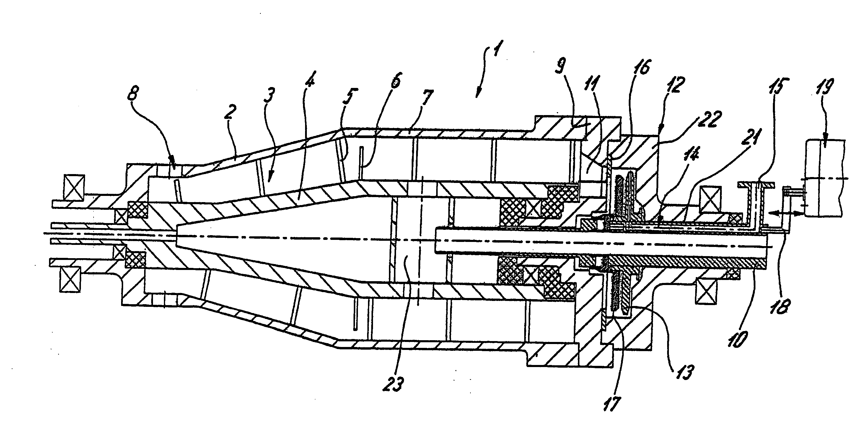
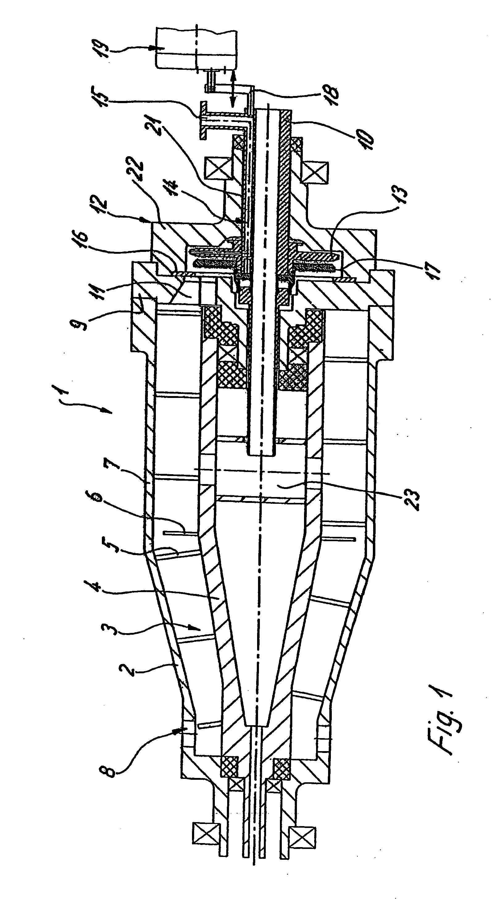
[0006]Accordingly, the throttling device which, in an operation during rotations of the drum, is continuously adjustable, and may be connected in front of the centripetal pump in the centripetal chamber section. The throttling device is assigned to or connected behind the at least one discharge opening, which additionally may be equipped with an overflow disk. This throttling device makes it possible to influence the liquid level in the drum of the centrifuge in addition to the operation of a baffle plate by throttling the liquid outlet cross-section. Thus, by changing the flow resistance between the overflows from the drum and the throttling device in front of the centripetal pump or the gripper, this surprisingly clearly optimizes the possibility of controlling and / or regulating the conditions in the centrifuge.
[0013]It is surprisingly advantageous to combine the centripetal pump with a movable, particularly axially adjustable
throttle disk in the drum because it thereby becomes possible, when a centripetal pump is used, to continuously regulate the
pool depth during the operation and thus adjust the optimal ratio between the flow in the centripetal chamber section and the
pool depth in the decanter drum without having to
throttle the discharge line.
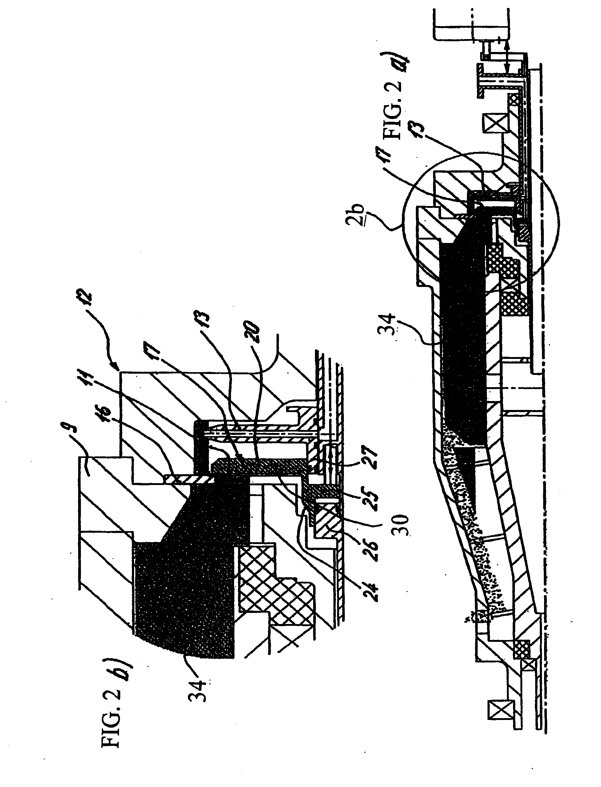
[0016]In the case of pulp, which is difficult to discharge, a hydraulic support is often required during the discharge by a Δp in front of and behind a baffle plate on the screw. If the regulating
diameter at the liquid discharge is rigidly adjusted to this value, penetrations of liquid can be expected on the solids side during the starting process because no sufficient solids closure has yet formed at the baffle plate. Inversely, the maximal pool depth / clarifying effect cannot be achieved when the adjustment of the regulating diameter is large. According to the present disclosure, by a combination of the throttle disk and the centripetal pump, an operation “with a shallow pool” can take place in a simple manner in the starting condition until a sufficient
bed formation or solids closure has taken place at the baffle plate in order to then increase the pool depth to the maximally possible value. The present disclosure, therefore, makes it possible to satisfactorily process also pulp by a centripetal pump, which pulp is difficult to discharge.
[0021]The throttle disk can easily be constructed to be stationary during the operation if it can be moved by a connecting rod which penetrates a stationary feeding
pipe not rotatable during the operation or a component connected with the feeding
pipe. In this case, the throttle disk is displaceably guided on the feeding
pipe and / or the centripetal pump.

