
Position detecting system and method of the same

a technology of position detection and detection system, applied in the direction of distance measurement, process and machine control, instruments, etc., can solve the problems of unavoidable hardware cost, unfavorable image processing, waste of money and time, etc., and achieve the effect of cleaning job in a short tim

Inactive Publication Date: 2008-06-26
IND TECH RES INST
View PDF17 Cites 16 Cited by
  • Summary
  • Abstract
  • Description
  • Claims
  • Application Information

AI Technical Summary

Benefits of technology

[0009]In view of the disadvantages of the prior art mentioned above, it is a primary objective of the present invention to provide a position detecting system and a method of the same, so as to reduce production costs.
[0010]It is another objective of the present invention to provide a position detecting system and a method of the same, so as to avoid repetitive cleansing jobs at the same place.
[0015]In summary, the position detecting system and the method of the same mainly involves the steps of: when a cleansing apparatus is traveling along a preset path, allowing an inertia sensing module to detect a displacement signal of the cleansing apparatus, allowing an obstacle sensing module to detect a distance signal of a distance between the cleansing apparatus and a nearby obstacle; allowing the signal processing module to convert the displacement signal detected by the inertia sensing module and the distance signal detected by the obstacle sensing module into an actual displacement path and an obstacle distance respectively; comparing the preset path with the actual displacement path and the obstacle distance to determine if the cleansing robot is repeatedly traveling at the same area, or if the cleansing robot is going to hit the obstacle; adjusting a traveling path based on the comparison results; allowing the control module to control traveling of the cleansing apparatus based on the adjusted traveling path, thereby avoiding repetitive cleansing at the same area.
[0016]Besides, the position detecting system and the method of the same are capable of allowing users to determine and input preset path based on nearby surroundings via an external device, therefore, at each of the different places for cleansing, the cleansing apparatus is capable of calculating an optimal traveling path from the stored preset path, therefore the cleansing apparatus can complete its cleansing job in a short time.

Problems solved by technology

Since the cleansing robots are incapable of detecting if a place has been cleaned over again, it wastes money and time unnecessarily.
To solve the aforementioned drawbacks, U.S. Pat. No. 6,732,826 discloses a cleansing robot and the cleansing robot's system and its application method, wherein a camera is used to take pictures of surroundings to determine positions; and since photo shooting and image process technologies are involved, high cost of hardware is certainly unavoidable; besides, image process consumes electricity and time.
The aforementioned robotic cleansing apparatus is capable of differentiating positions by making use of optical sensors or acoustic sensors to dodge any obstacles and places where have been cleansed; however, in order to make use of the robotic cleansing apparatus, for detecting purpose, a plurality of optical emitters must be installed at many different points of the room to be cleaned, thereby increasing cost.

Method used


Image

  • Position detecting system and method of the same
  • Position detecting system and method of the same
  • Position detecting system and method of the same

Examples


Embodiment Construction

[0021]The following illustrative embodiments are provided to illustrate the disclosure of the present invention, these and other advantages and effects can be apparently understood by those in the art after reading the disclosure of this specification. The present invention can also be performed or applied by other different embodiments. The details of the specification may be on the basis of different points and applications, and numerous modifications and variations can be devised without departing from the spirit of the present invention.

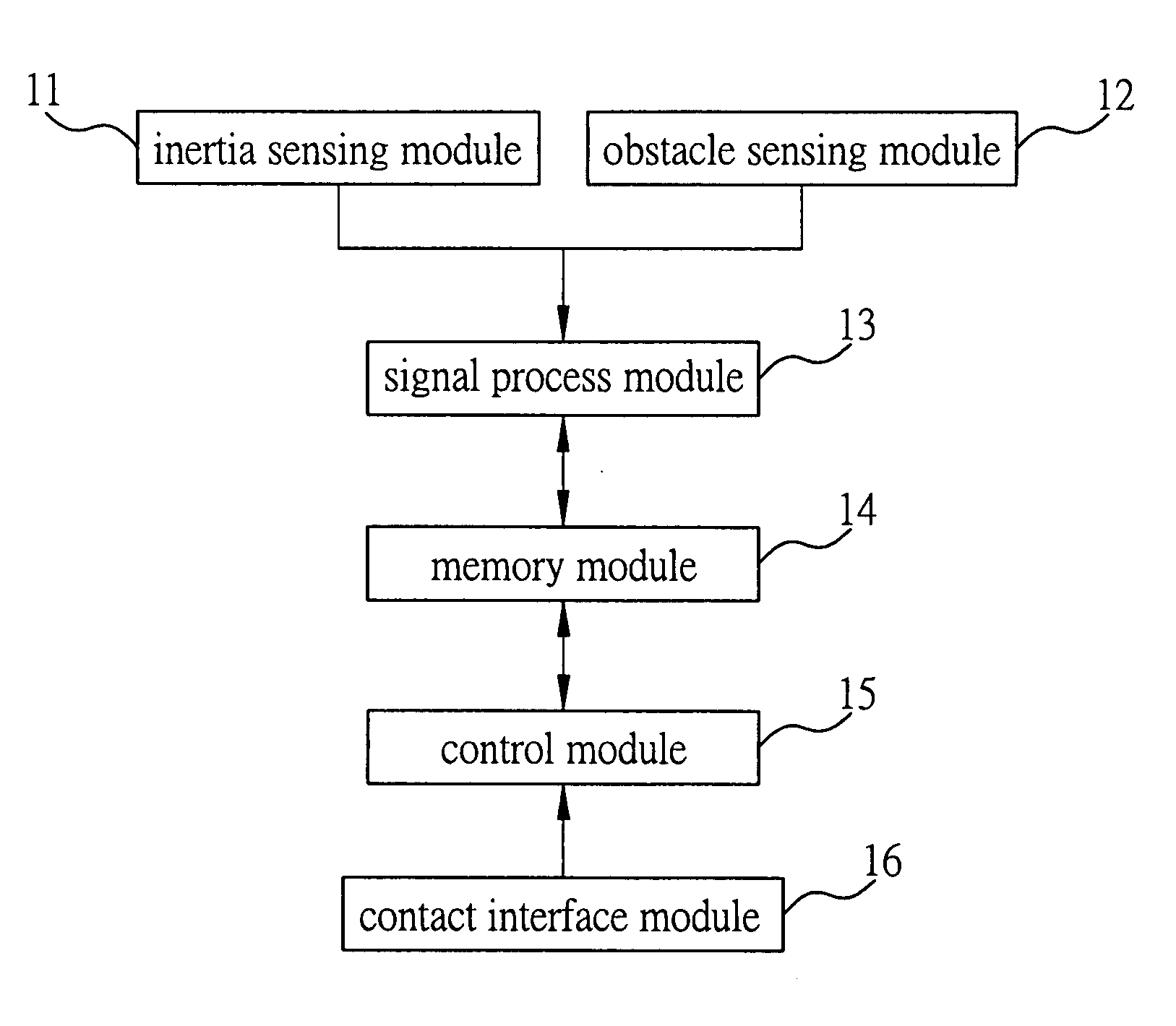
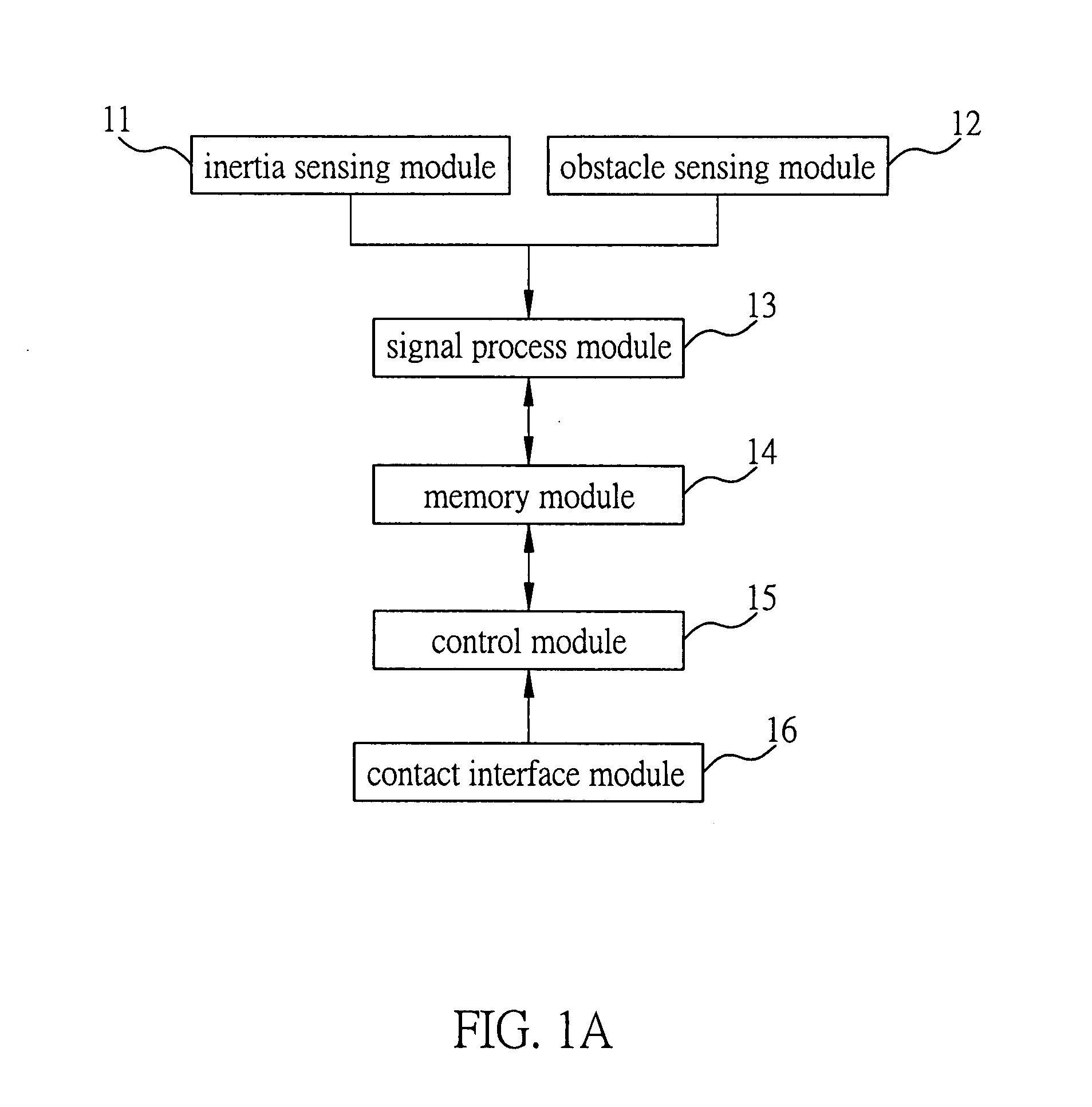
[0022]Please refer to FIG. 1A, which is a schematic view of a position detecting system according to the present invention.

[0023]As shown in the drawing, the position detecting system comprises: an inertia sensing module 11, an obstacle sensing module 12, a signal processing module 13, a memory module 14, and a control module 15; the position detecting system is applicable to a cleansing apparatus for detecting and positioning purposes, the clean...


PUM


Abstract

A position detecting system and a method of the same are disclosed according to the present invention as follows: an inertia sensing module and an obstacle sensing module are adapted to detect a displacement signal of a cleansing apparatus and a distance signal of a distance between the cleansing apparatus and an obstacle respectively; and then a signal processing module is adapted to convert the displacement signal and the distance signal into an actual displacement path and an obstacle distance respectively, and then compare the actual displacement path and the obstacle distance with a preset path respectively to determine if the cleansing apparatus is traveling at the same place over again, or if the cleansing apparatus is going to hit the obstacle, and then the signal processing module will adjust a traveling path based on comparison results; and a control module is adapted to control traveling of the cleansing apparatus based on the adjusted traveling path. Hence, the cleansing apparatus is capable of repeating the foregoing steps for detecting and positioning purposes at any time during a cleansing process, thereby avoiding repetitive cleaning at the same place.

Description

BACKGROUND OF THE INVENTION[0001]1. Field of the Invention[0002]This invention generally relates to position detecting systems and methods of the same, and more specifically, to a position detecting system and a method of the same, which are applicable to cleansing apparatuses.[0003]2. Description of Related Art[0004]At present, sensors are applied in most cleansing robots to detect signals and determine if a traveling path should be changed. Since the cleansing robots are incapable of detecting if a place has been cleaned over again, it wastes money and time unnecessarily.[0005]To solve the aforementioned drawbacks, U.S. Pat. No. 6,732,826 discloses a cleansing robot and the cleansing robot's system and its application method, wherein a camera is used to take pictures of surroundings to determine positions; and since photo shooting and image process technologies are involved, high cost of hardware is certainly unavoidable; besides, image process consumes electricity and time.[0006]...

Claims


Application Information

Patent Timeline
IPC IPC(8): G05D1/00
CPCG05D1/0219G05D1/0238G05D2201/0203G05D1/0274G05D1/027
Inventor YU, REN-YUANCHEN, YUNG-YUCHANG, SHYANG-JYEWANG, SHIH-HAOTSAI, MING-JYE
Owner IND TECH RES INST
Learn More