Telescopic hand tool

Inactive Publication Date: 2008-07-03
CHEN CHIA YU
View PDF10 Cites 8 Cited by
  • Summary
  • Abstract
  • Description
  • Claims
  • Application Information

AI Technical Summary

Benefits of technology

[0006]The main characteristics of the invention are a main body, a bar and a positioning device. The bar is provided with an axial hole bored axially from its one end for engaging with a telescopic bar of the main body, and a sliding groove dug around its surface, bored with a ball hole. The positioning device is composed of a restricting knob, a compression spring and a restricting plate. The restricting knob can slide restrictively along the sliding groove by means of a restricting block so as to let the main body move in the bar axially. The compression spring can push elastically the restricting knob back to its original position to pr

Problems solved by technology

But, it is so inconvenient that the controlling cover 13 has to be cont

Method used


Image

  • Telescopic hand tool
  • Telescopic hand tool
  • Telescopic hand tool

Examples


Embodiment Construction

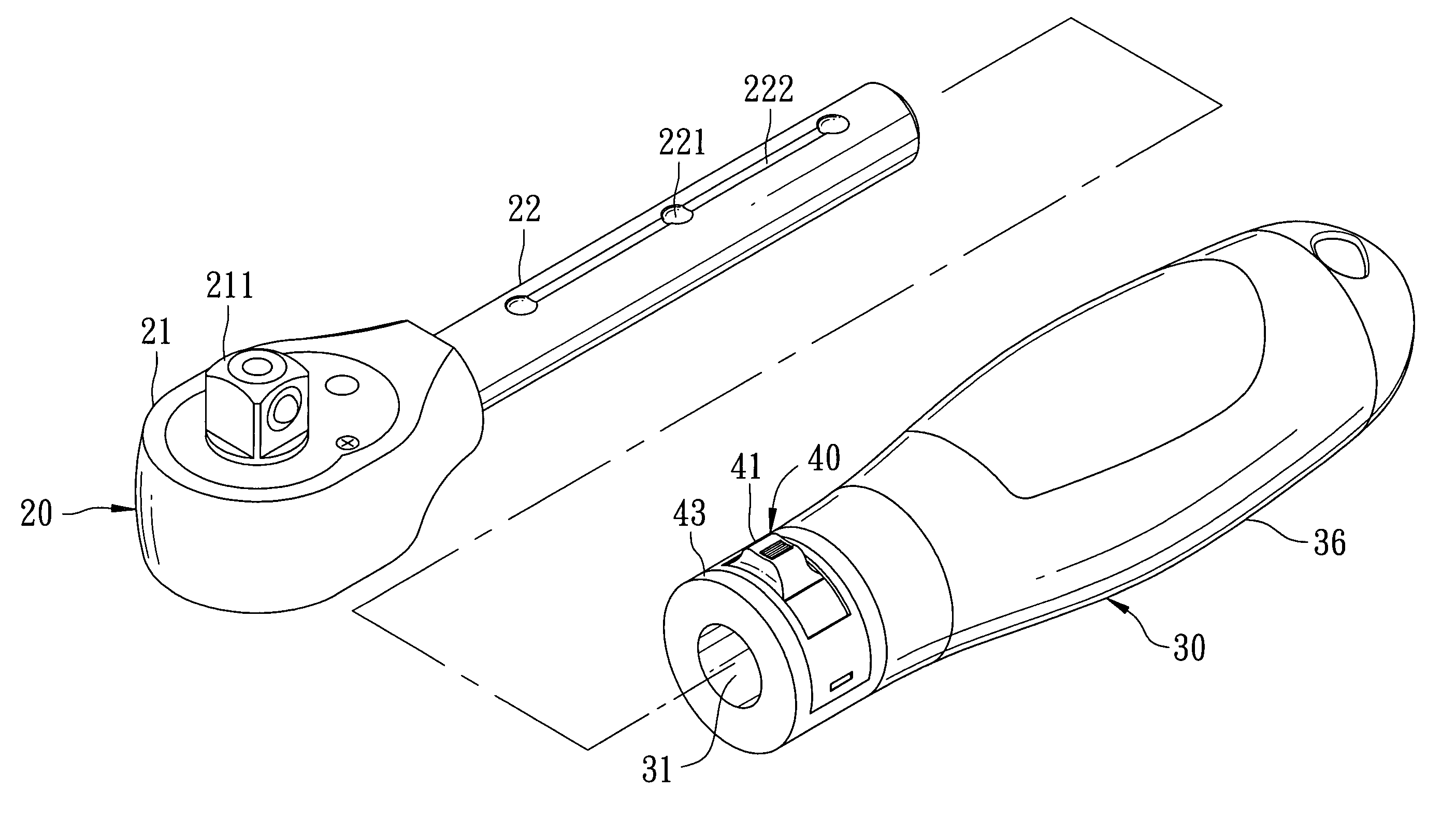
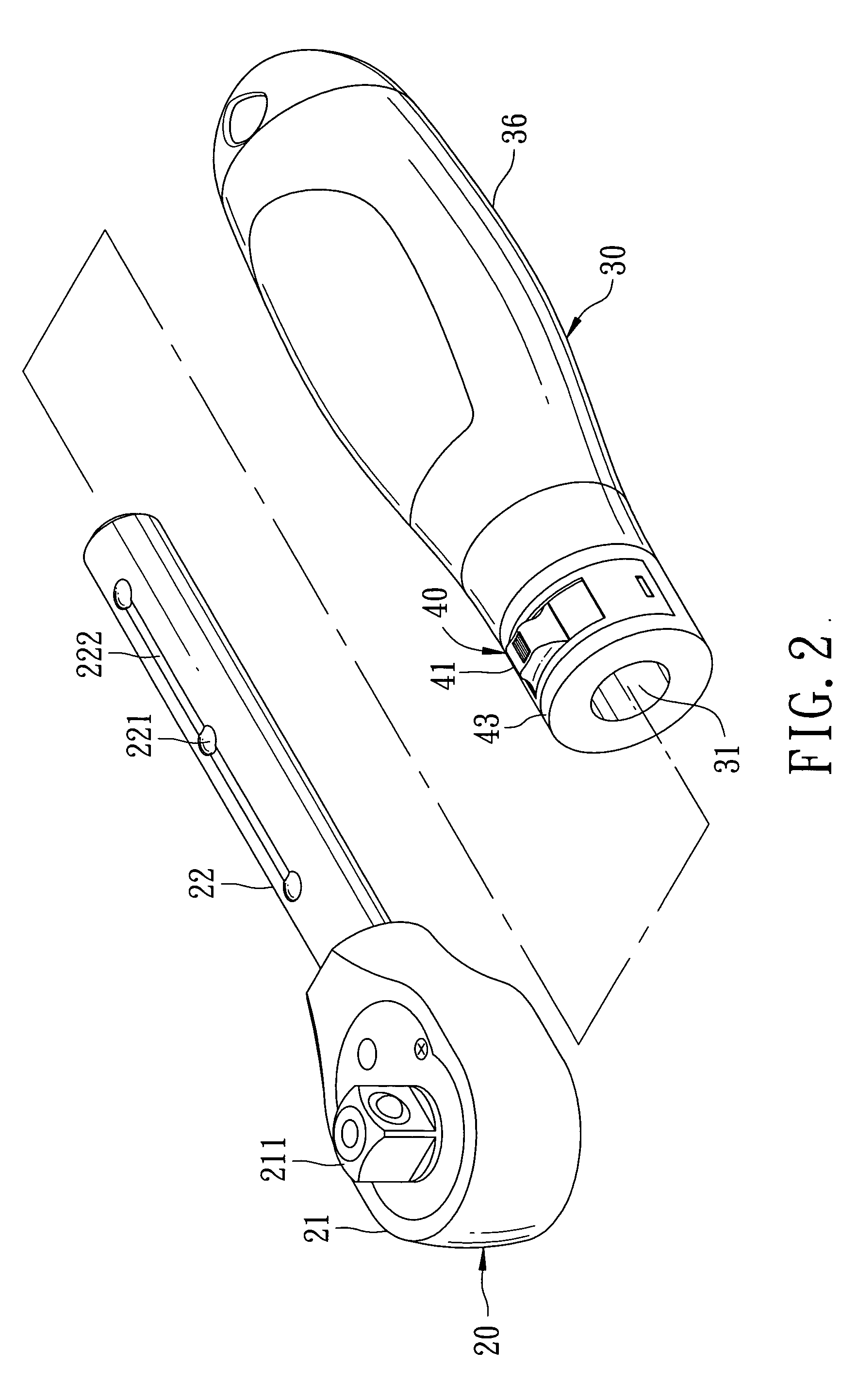
[0016]As shown in FIGS. 2 and 3, a first preferred embodiment of a telescopic hand tool in the present invention is composed of a main body 20, a bar 30 and a positioning device 40.

[0017]The main body 20 is provided with a working head 21 formed in its front portion and a telescopic bar 22 formed in its rear portion. The working head 21 is provided with a ratchet set 211 for engaging with a tool. The telescopic bar 22 formed cylindrical is provided with plural restricting ball holes 221 bored axially with equidistance, and a shallow groove 222 concaved with a depth lower than that of the restricting ball holes 221, for communicating with the restricting ball holes 221.

[0018]The bar 30 formed as an annular column is provided with an axial hole 31 bored axially from its one end for engaging with the telescopic bar 22 of the main body 20, a sliding groove 32 dug near the opening of the axial hole 31 to form as a two-step ladder, and a ball hole 33 bored in the sliding groove 32 for a s...


PUM


Abstract

A telescopic hand tool consists of a main body, a bar and a positioning device. The bar possesses an axial hole bored axially from its one end for engaging with a telescopic bar of the main body, and a sliding groove dug around its surface, bored with a ball hole. The positioning device includes a restricting knob, a compression spring and a restricting plate. The restricting knob can slide restrictively along within the sliding groove by means of a restricting block so as to let the main body move in the bar axially. The compression spring can push elastically the restricting knob back to its original position to press on a steel ball restricted in a restricting ball hole of the main body, keeping the main body locked restrictively in the bar.

Description

BACKGROUND OF THE INVENTION[0001]1. Field of the Invention[0002]This invention relates to a hand tool, particularly to one that can be adjusted telescopically and kept immovably by means of a knob able to re-position automatically.[0003]2. Description of the Prior Art[0004]Commonly, as shown in FIG. 1, a conventional telescopic hand tool 10 is composed of a main body 11, a bar 12, a controlling cover 13, a compression spring 14 and a C-shaped lock washer 15. The main body 11 is provided with plural restricting ball holes 111 bored axially with equidistance and a shallow groove 112 concaved to communicate with the restricting ball holes 111. The bar 12 is provided with a positioning hole 121 bored at its one end for a positioning ball 122 to stay on, and an annular slot 123 bored around a certain spot. The controlling cover 13 is provided with a controlling groove 131 and an accommodating groove 132 formed respectively on its inner wall of two opposite sides and spaced apart by a blo...

Claims


Application Information

Patent Timeline
IPC IPC(8): A45C13/28
CPCY10T16/473B25G1/043
Inventor CHEN, CHIA YU
Owner CHEN CHIA YU
Why Eureka
Try Eureka