Shift-drum speed change mechanism

a technology of speed change mechanism and shift drum, which is applied in the direction of gearing control, gearing element, belt/chain/gearing, etc., can solve the problems of fixed order of four speed change states, sliding to the position where the slider is connected to the corresponding speed change gear,

Active Publication Date: 2017-01-31
KANZAKI KOKYUKOKI MFG
View PDF9 Cites 2 Cited by
  • Summary
  • Abstract
  • Description
  • Claims
  • Application Information

AI Technical Summary

Benefits of technology

[0020]The present invention has been conceived in view of the conventional art described above, and an object of the present invention is to provide a shift-drum speed change mechanism wherein an operation shaft by which a drum is supported so as to be incapable of relative rotation is rotated around the axis to move a shift fork and a slider in the axial direction by a guide groove formed in the drum and cause the slider to be engaged with the corresponding speed change member to perform a speed change operation, with which manual operation on the operation shaft can be completed as promptly as possible.
[0023]Moreover, the shift-drum speed change mechanism of the present invention makes it possible to accurately and stably have the first drum positioned at a reference position defined by the first stopper member for the first drum, thereby accurately and stably performing a position control of the first slider.
[0049]Moreover, another object of the present invention is to provide a shift-drum speed change mechanism which includes a drum member that has first and second guide grooves into which the engagement pins of the first and second shift forks are inserted, respectively, and that is capable of taking at least a reference rotational position, a rotational position more toward one side around the axis than the reference rotational position is, and a rotational position more toward the other side around the axis than the reference rotational position is, and provides speed change states in accordance with the rotational positions of the operated drum member, the shift-drum speed change mechanism capable of performing a speed change operation from a speed change state corresponding to the rotational position on one side of the reference rotational position around the axis or from a speed change state corresponding to the rotational position on the other side of the reference rotational position around the axis to a speed change state corresponding to the reference rotational position, and also capable of performing a speed change operation between a speed change state corresponding to the rotational position on one side around the axis and the speed change state corresponding to the rotational position on the other around the axis without arriving at the speed change state corresponding to the reference rotational position.
[0051]According to the shift-drum speed change mechanism of the present invention, it is possible to perform a normal speed change operation in which a first-side-around-axis speed change state (for example, a neutral state) corresponding to the rotational position of the drum member on one side of the reference rotational position around the axis or a second-side-around-axis speed change state (for example, a parking state) corresponding to the rotational position of the drum member on the other around the axis is shifted to a reference speed change state (for example, a reverse state) corresponding to the reference rotational position, and also possible to perform a speed change operation in which the first-side-around-axis speed change state and the second-side-around-axis speed change state are shifted from each other without arriving at the reference speed change state.
[0067]In light of this point, a shift-drum speed change mechanism is desired in which a shift fork and a slider are moved in the axial direction by a guide groove formed in a drum in accordance with the rotational operation around the axis of an operation shaft that supports the drum so as to be incapable of relative rotation and thereby the slider is engaged with the corresponding speed change member to provide a desired speed change state, and which is capable of exerting a detent action for locking the operation shaft at a desired operational position around the axis by a detent mechanism, and, further, capable of exerting a pushing force on the slider toward a speed change position without requiring additional components when the slider is in a speed change incomplete state from the neutral position toward the speed change position.

Problems solved by technology

However, if the circumferential positions of the engagement part of the slider and the engagement part of the corresponding speed change gear do not match (i.e., if the projections, or the depressions, of the engagement parts of the slider and the speed change member face each other), the slider cannot be pushed to the position where the slider is connected to the corresponding speed change gear.
In this way, the conventional shift-drum speed change mechanism can selectively provide four speed change states of a forward high-speed state, a forward low-speed state, a parking state, and a reverse state by operating the shift spindle around the axis, but is problematic in that the order of the four speed change states are fixed.

Method used


Image

  • Shift-drum speed change mechanism
  • Shift-drum speed change mechanism
  • Shift-drum speed change mechanism

Examples


Embodiment Construction

[0099]Below, one embodiment of the shift-drum speed change mechanism of the present invention will now be described with reference to the appended drawings.

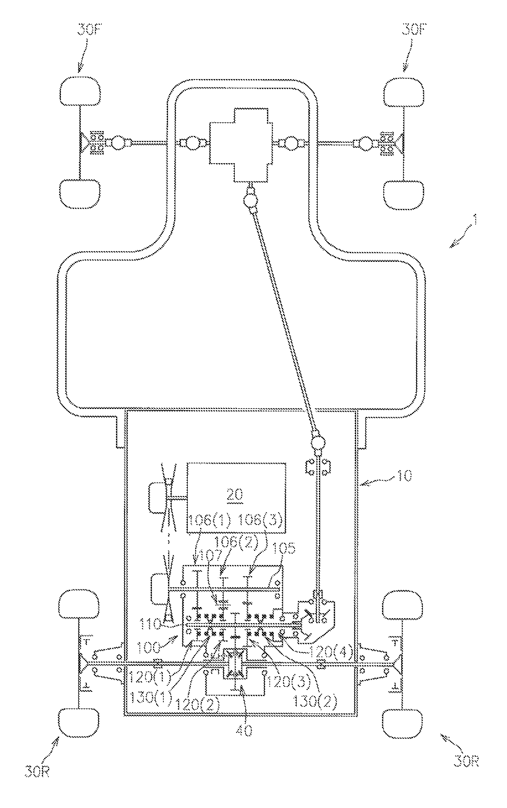
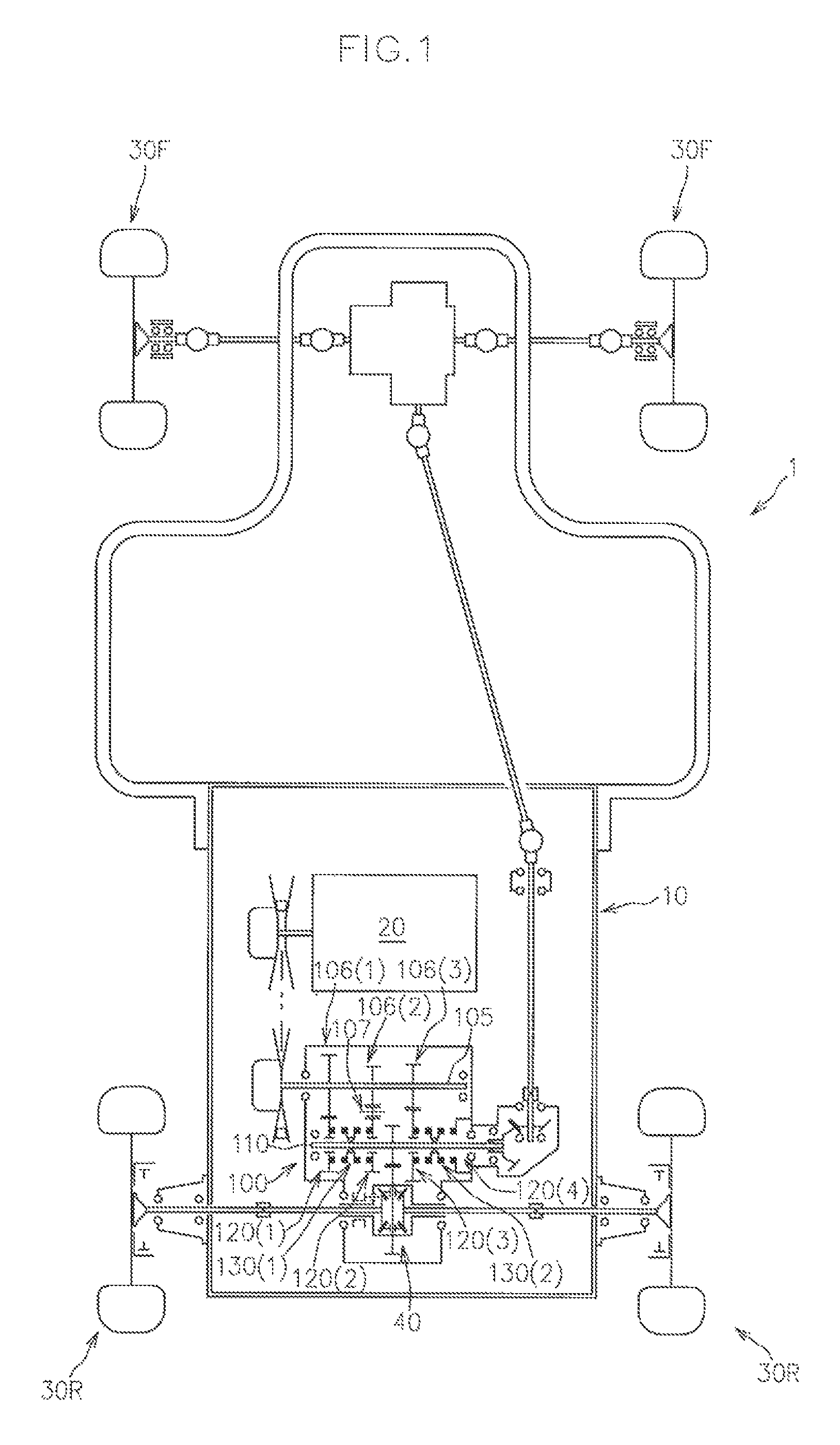
[0100]FIG. 1 shows a schematic view of the power transmission of a utility vehicle 1 to which a shift-drum speed change mechanism 100 of this embodiment is applied.

[0101]First, a general configuration of the utility vehicle 1 will now be described with reference to FIG. 1.

[0102]As shown in FIG. 1, the utility vehicle 1 comprises a vehicle body 10, an engine 20 supported by the vehicle body 10, front wheels 30F and rear wheels 30R supported by the vehicle body 10, and the shift-drum speed change mechanism 100 disposed in the driveline from the engine 20 to the wheels that serve as drive wheels among the front wheels 30F and the rear wheels 30R.

[0103]In this embodiment, both front wheels 30F and rear wheels 30R serve as drive wheels in the utility vehicle 1 as shown in FIG. 1

[0104]Specifically, the utility vehicle 1 has right-and-l...


PUM


Abstract

A shift-drum speed change mechanism includes a first drum spring biasing a first drum toward a first side in an axial direction, which is a side on which a first slider comes into contact with a first speed change member, a first fork spring biasing a first shift fork toward a second side in the axial direction, which is a side opposite to the first side in the axial direction, with a weaker biasing force than the first drum spring, and a first stopper member for the first drum, defining an end of movement of the first drum toward the first side in the axial direction.

Description

BACKGROUND OF THE INVENTION[0001]Field of the Invention[0002]The present invention relates to a shift-drum speed change mechanism.[0003]Related Art[0004]Shift-drum speed change mechanisms have been proposed and used as speed change mechanisms that are disposed in the driveline of utility vehicles, all-train vehicles, off-road vehicles, etc.[0005]For example, JP2014-070650A (hereinafter referred to as Patent Document 1, which has a corresponding U.S. application publication No. US 2014 / 0083228A1) discloses a shift-drum speed change mechanism comprising an operation shaft rotated around the axis; a drum supported by the operation shaft so as to be incapable of relative rotation and provided with, on the outer circumferential surface, a first guide groove for switching between high and low speeds and a second guide groove for switching between forward and reverse; a first shift fork having a first engagement pin inserted into the first guide groove; a second shift fork having a second ...

Claims


Application Information

Patent Timeline
Patent Type & Authority Patents(United States)
IPC IPC(8): F16H59/04F16H63/18F16H61/26
CPCF16H63/18F16H61/26F16H57/0018F16H59/02F16H63/30F16H2306/00F16H63/3416F16H63/38F16H2063/3089
Inventor TSUKAMOTO, MICHIONISHIMOTO, SHUJIMURASHIMA, DAISUKE
Owner KANZAKI KOKYUKOKI MFG
Why Eureka
Try Eureka