
Apparatus, system, and method for rapid design of emissions component installations

a technology for emissions components and installation designs, applied in the direction of manufacturing tools, machines/engines, safety devices, etc., can solve the problems of affecting the end user of a vehicle or application, the difficulty of forcing installation on the original equipment manufacturer (oem), and the secondary effect of new emissions technologies on engine operation, emissions, fuel economy, durability, etc., to achieve the effect of improving the design of emissions component installation

Active Publication Date: 2008-07-03
CUMMINS FILTRATION IP INC
View PDF9 Cites 17 Cited by
  • Summary
  • Abstract
  • Description
  • Claims
  • Application Information

AI Technical Summary

Benefits of technology

[0040]FIG. 13 is a schematic flow chart illustrating a method to enhance an emissions component installation design in accordance with the present invention.

Problems solved by technology

The result has been a proliferation of engine controls and components which have forced installation difficulties onto original equipment manufacturers (OEMs) using these engines.
A primary difficulty for OEMs is that they must integrate the engine intake and exhaust tubing with a vehicle or application.
These complications force OEMs to spend time engineering and designing the tubing for each engine into each application.
Another difficulty for OEMs is that new emissions technologies have secondary effects on engine operation, emissions, fuel economy, and durability.
This difficulty also affects the end user of a vehicle or application.
For example, a particular emissions technology may affect the oil change interval, and thereby require a truck fleet to change some operating logistics in response.
However, the effects of new emissions technologies and the available mitigating technologies are not known by the OEM designer of the application.
Further, since many of the mitigating technologies are more expensive than conventional counterparts, the original designer of the emissions technology may not recommend or include a mitigating technology for every application.
Therefore, the use of mitigating technologies requires hours of research to answer questions that the OEM or end user may not even know to ask.

Method used


Image

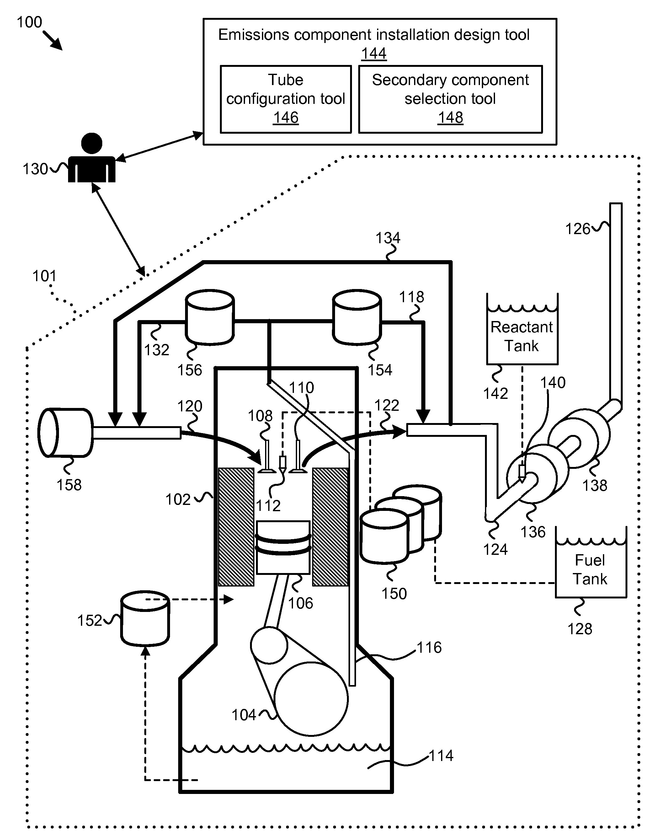
  • Apparatus, system, and method for rapid design of emissions component installations
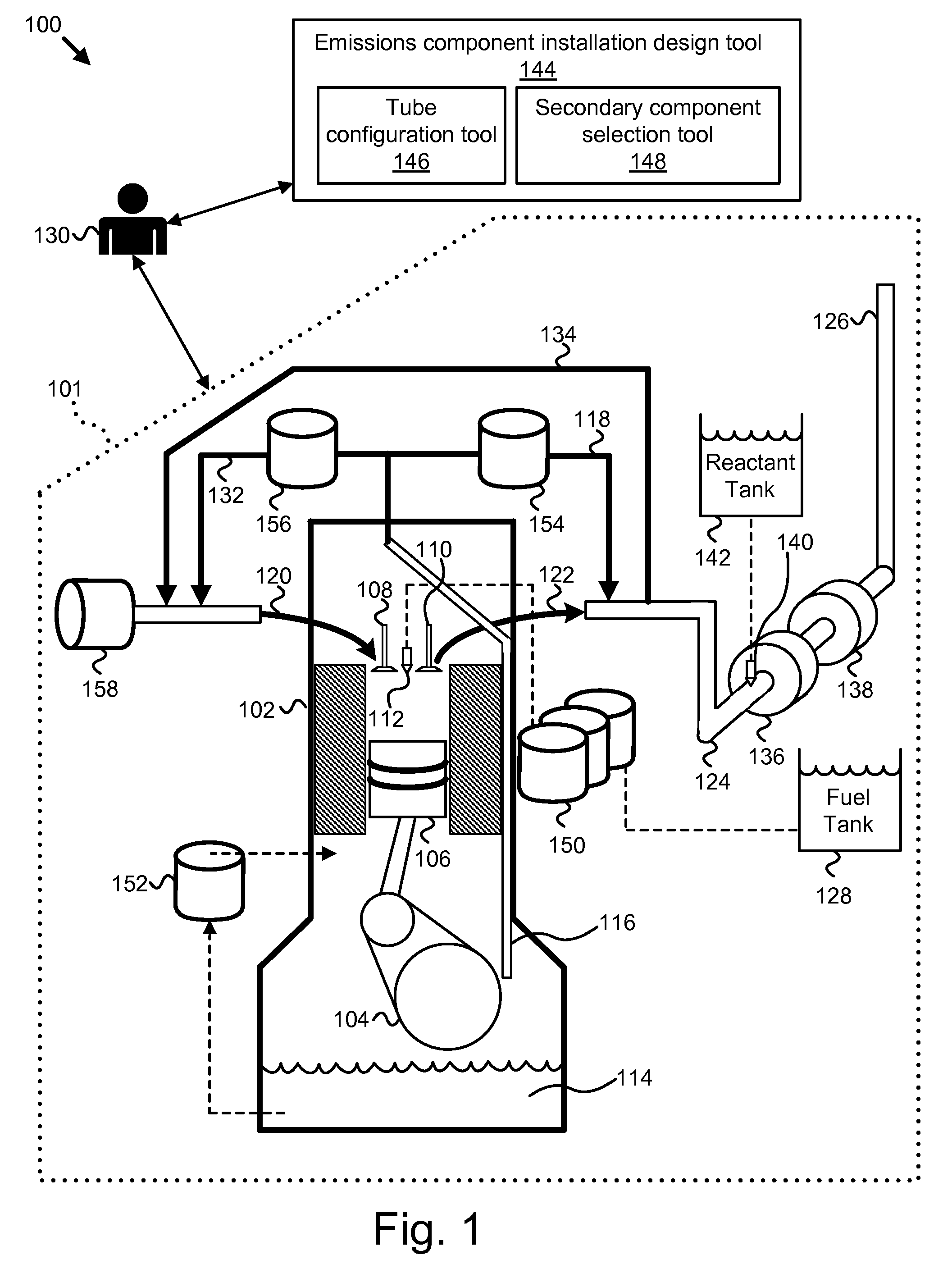
  • Apparatus, system, and method for rapid design of emissions component installations
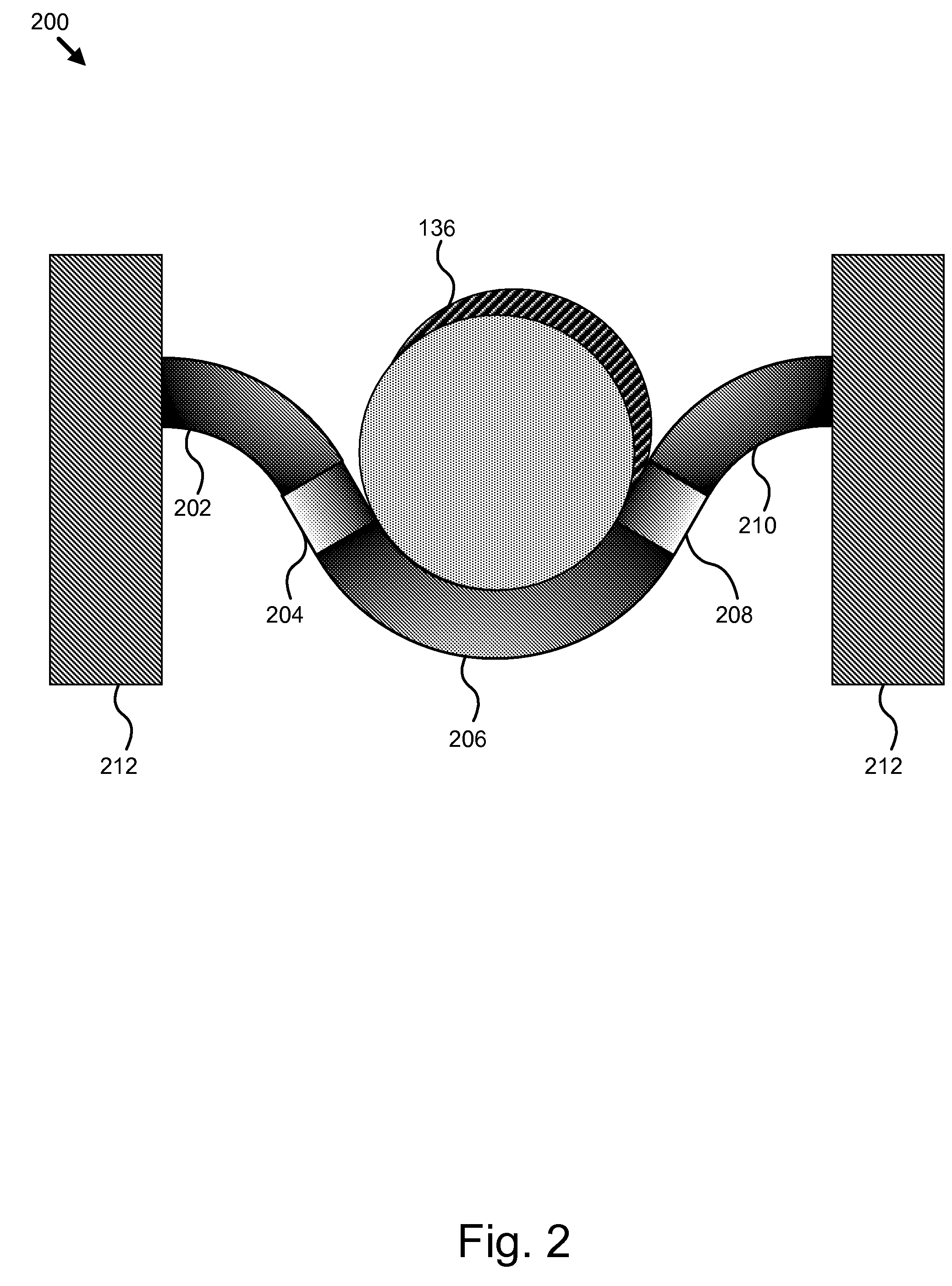
  • Apparatus, system, and method for rapid design of emissions component installations

Examples


Embodiment Construction

[0041]Many of the functional units described in this specification have been labeled as modules, in order to more particularly emphasize their implementation independence. For example, a module may be implemented as a hardware circuit comprising custom VLSI circuits or gate arrays, off-the-shelf semiconductors such as logic chips, transistors, or other discrete components. A module may also be implemented in programmable hardware devices such as field programmable gate arrays, programmable array logic, programmable logic devices or the like.

[0042]Modules may also be implemented in software for execution by various types of processors. An identified module of executable code may, for instance, comprise one or more physical or logical blocks of computer instructions which may, for instance, be organized as an object, procedure, or function. Nevertheless, the executables of an identified module need not be physically located together, but may comprise disparate instructions stored in d...


PUM

PropertyMeasurementUnit
bend radiusaaaaaaaaaa
outer diameteraaaaaaaaaa

Abstract

An apparatus, system, and method are disclosed for rapid design of emissions component installations. The method assists in the rapid design of emissions component installations by: interpreting a tube design input which may be an exhaust pipe with one or more aftertreatment components, calculating a final tube design and tube drawing, determining the manufacturability of the final tube design, determining the manufacturing cost of the final tube design, and displaying the drawing, manufacturability result, and manufacturing cost to a user. The method also evaluates the final tube design for portions that can be replaced with a more cost effective alternative. The method also receives the emissions reduction features of the installation from the user, and recommends secondary components to mitigate operational consequences, such as reduced fuel economy or reduced oil change intervals, of the emissions reduction features. Thus, the invention allows a user to quickly design an installation of an emissions component with an internal combustion engine into a target application.

Description

BACKGROUND OF THE INVENTION[0001]1. Field of the Invention[0002]This invention relates to the rapid design of emissions component installations, and more particularly relates to installing emissions components with internal combustion engines.[0003]2. Description of the Related Art[0004]Emissions standards for combustion engines have been rapidly advancing over the past few years. Engine manufacturers have responded with a variety of technologies designed to meet the new emissions standards. The result has been a proliferation of engine controls and components which have forced installation difficulties onto original equipment manufacturers (OEMs) using these engines.[0005]A primary difficulty for OEMs is that they must integrate the engine intake and exhaust tubing with a vehicle or application. The OEM may also need to integrate tubular members that may be structural support elements of the application. Various emissions technologies alter the engine or exhaust locations for each ...

Claims


Application Information

Patent Timeline
Patent Type & Authority Applications(United States)
IPC IPC(8): B60K13/04
CPCF01N3/035F01N3/2066F01N13/08F01N2450/00Y10T29/5185Y10T29/5199Y10T29/53652Y10T29/49398F01N13/009Y02A50/20
Inventor CLEVENGER, JOHN W.GIBSON, DONALD A.SARCONA, DAVIDSENETAR, MICHAEL J.
Owner CUMMINS FILTRATION IP INC
Learn More