Continuous feeder

Inactive Publication Date: 2008-07-03
SUN YIEH IND
View PDF4 Cites 1 Cited by
  • Summary
  • Abstract
  • Description
  • Claims
  • Application Information

AI Technical Summary

Benefits of technology

[0006]The main purpose of the present invention is to solve the problems described above. According to the present invention, not only the moving distance of material in processing can be precisely adjusted for continuously and accurately driving the material to the operation tool, but the method for driving the material also can be selected to be pull or push in response to the hardness degree of material.
[0007]According to the object described above, the present invention provides a continuous feeder used to precisely drive a material to an operation tool for processing includes a base having a push-forward rejecting element and a push-backward rejecting element; a moving unit having a fixing clip, which is driven by a m

Problems solved by technology

Currently, the conventional feeders have two problems urgently to be solved: one is that the movement of the material to be processed can not be driven precisely so that the problem of accumulated tolerance is always existed, and the other is the method for feeding the material can not be switched to be pull or push according to the property, such as soft or hard, of the material.
Therefore, since the soft material is continuously rolled up, if each second has an error of 0.1 mm, an error of 6 cm will be produced after 1 minute of rolling-up.
However, when the rolling shaft drives the material, an error of 5 cm will be produced after moving the material for 5 m if each turn of the rolling shaft has

Method used


Image

  • Continuous feeder
  • Continuous feeder
  • Continuous feeder

Examples


first embodiment

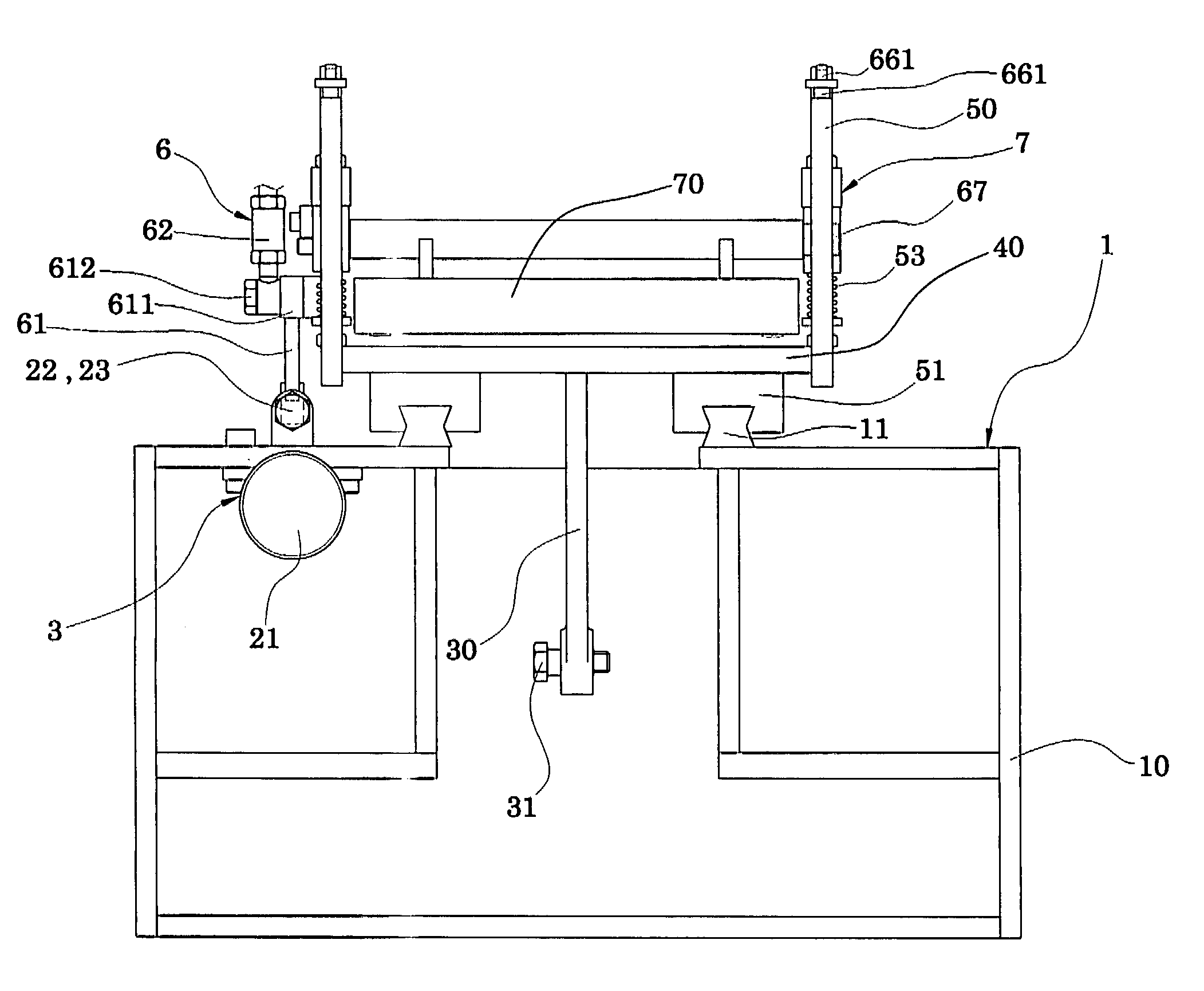
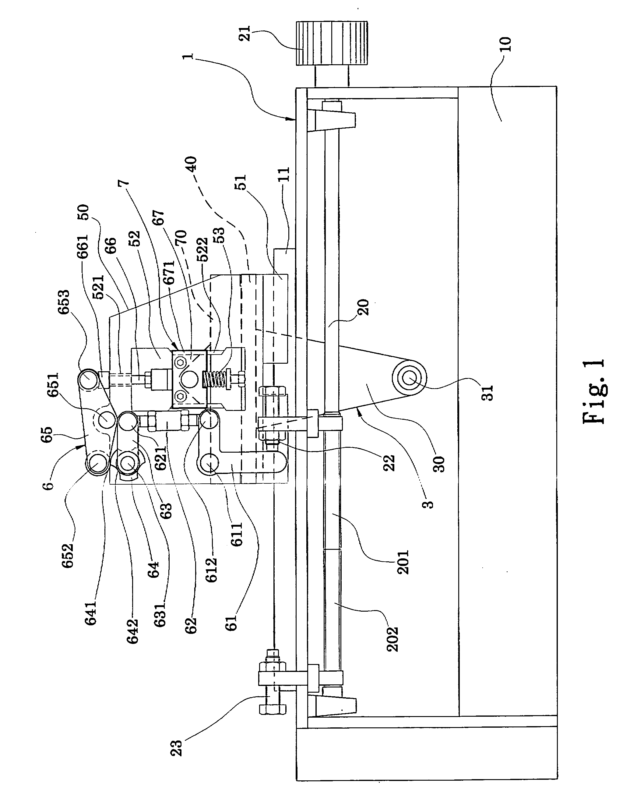
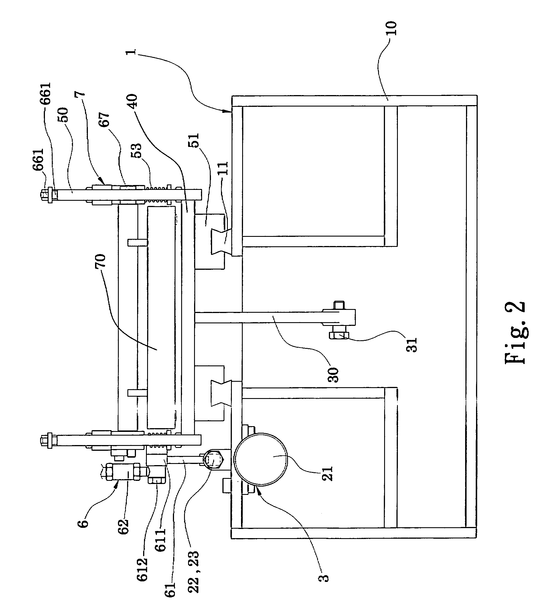
[0015]Please refer to FIGS. 1˜2, which are respectively a lateral view and a partial front view showing a continuous feeder according to the present invention, and FIGS. 3A˜3D, which are lateral views showing a first kind of operations of the continuous feeder in a first embodiment according to the present invention. As shown, the continuous feeder of the present invention includes a base 1, which has a seat 10 having an adjusting shaft 20 thereon with a sliding track 11 at the top of the shaft, wherein the adjusting shaft 20 has a reverse thread region 201 and an obverse thread region 202 which respectively have, mounted thereon, a push-forward rejecting element 22 and a push-backward rejecting element 23 overhead the seat 10, so that through turning an adjusting knob 21 at the front end of the adjusting shaft 20, the push-forward rejecting element 22 and the push-backward rejecting element 23 can reversely move synchronously; a moving unit 3, which has a driving seat 30 having a p...

second embodiment

[0020]Please refer to FIG. 6, which is a lateral view showing the continuous feeder in a second embodiment according to the present invention. As shown, the difference between FIG. 6 and the previous figures is that, between the cam disc 80 and the motor 90, a belt 803 can be used for connection and driving.


PUM


Abstract

The present invention is a continuous feeder which, through a power source, can continuously drive a fixing clip to move back and forth equidistantly and also a mobile clip at the top of the fixing clip, so that when the fixing clip arrives the return point, the material can be downwardly clipped or upwardly released for achieving a continuous feeding. The present invention not only can precisely adjust the moving distance of material in processing for continuously and accurately driving the material to the operation tool, but also can change the driving method for the material to be pull or push in response to the hardness degree of the material.

Description

FIELD OF THE INVENTION[0001]The present invention is related to a continuous feeder, and more particularly to a continuous feeder which can precisely drive the material to move to the operation tool for processing.BACKGROUND OF THE INVENTION[0002]Currently, the conventional feeders have two problems urgently to be solved: one is that the movement of the material to be processed can not be driven precisely so that the problem of accumulated tolerance is always existed, and the other is the method for feeding the material can not be switched to be pull or push according to the property, such as soft or hard, of the material.[0003]First, relating to the problem of accumulated tolerance, the reason is that, currently, no matter the feeding material is pushed or pulled, the turning motive force is always employed. For the pulling method, a rolling at the end is employed which may change the rolling speed cooperating with the variable factors (such as the rolled thickness generated from r...

Claims


Application Information

Patent Timeline
IPC IPC(8): B21D43/04
CPCB65H2403/53B65H20/18
Inventor CHEN, WEN-CHENG
Owner SUN YIEH IND
Why Eureka
Try Eureka